

Web edition, unofficial copy
Aquasport 52 Owner’s Manual with Safety and Installation Information
AQUASPORTS POOLS, LLC.
OWNER’S MANUAL
AQUASPORT
ABOVEGROUND RESIDENTIAL TYPE O NON-DIVING SWIMMING POOL EXTRUDED ALUMINUM, PAINTED 52″ HIGH, PANEL WALL POOLS ROUND AND OVAL INSTALLATION INSTRUCTIONS
THESE POOLS ARE MADE FOR AND SHALL ONLY BE SOLD AND INSTALLED FOR FLAT BOTTOM ABOVE GROUND POOLS
THESE PRODUCTS ARE MANUFACTURED IN ACCORDANCE WITH VOLUNTARY STANDARDS ANSI/NSPI-4 DATED 1999 OR LATEST UPDATE
AQUASPORTS POOLS, LLC. IS IN NO WAY AFFILIATED WITH ANY PROFESSIONAL POOL INSTALLER. THEREFORE, AQUASPORTS POOLS, LLC. CANNOT ASSUME ANY RESPONSIBILITY FOR ERRORS IN INSTALLATION BY THE HOMEOWNER OR SAID PROFESSIONAL INSTALLER. IF YOU HAVE THE POOL, DECKING AND FENCING INSTALLED BY OTHERS, PLEASE SUPERVISE TO BE SURE THEY COMPLY WITH PROPER INSTRUCTION TECHNIQUES AS SHOWN.
ISSUED MARCH 1, 1995. TEXT UPDATED DECEMBER 1, 2003.
Swimming pool safety introduction
Web edition by MGK Pools, Winchendon, Massachusetts. Source: https://mgkpools.com/aquasport-52/owners-manual/
SWIMMING POOL SAFETY
INTRODUCTION
Congratulations on bringing swimming enjoyment to your family. Swimming is great fun for youngsters and grownups alike. Having your own above ground pool is a satisfying delight, yet, there are a number of important above ground pool safety rules you must remember and enforce AT ALL TIMES. Failure to understand and enforce these safety reminders can result in SERIOUS PERMANENT INJURIES, including, paralysis from a broken neck and damage to the spinal cord or death from drowning or electrocution. You as the owner have the most important role in reminding users of this above ground pool how to use it safely.
Labels printed in this drawing
- DANGER (warning triangle)
- NO JUMPING!
- NO DIVING!
- Shallow water.
- You can be permanently injured.
- DO NOT DEFACE, COVER, OR PAINT OVER THIS SIGN
DANGER
SHALLOW WATER
NEVER DIVE, SLIDE or JUMP into this ABOVE GROUND / ON GROUND POOL. ALWAYS supervise all users, ESPECIALLY CHILDREN to prevent INJURY or DROWNING.
PROVIDE MEANS OF INGRESS AND EGRESS FROM POOL BY MEANS OF LADDERS/STAIRCASES/ STEPS ETC
PERMANENT INJURY, PARALYSIS or DEATH can RESULT if you FAIL to OBEY this WARNING. This ABOVE GROUND / ON GROUND POOL is designed for SWIMMING AND WADING ONLY! It is not DEEP ENOUGH for SAFE DIVING, SLIDING or JUMPING.
These Safety Reminders require pool users to EXERCISE COMMON SENSE. ALWAYS use COMMON SENSE in your use of this product in order to AVOID RISKS ASSOCIATED with electricity, and water to avoid serious injury resulting from JUMPS, DIVES, SLIDES, SLIPS, FALLS and ELECTRIC SHOCK.
SAVE THESE INSTRUCTIONS!
DANGER
FAILURE to HEED THESE WARNINGS can RESULT in PERMANENT INJURY, PARALYSIS, or DEATH
-
NEVER DIVE, SLIDE or JUMP into this ABOVE GROUND / ON GROUND SWIMMING POOL. It is too shallow for safe jumping and diving.
-
NEVER DIVE, SLIDE or JUMP from the LADDER, DECK, TOP LEDGE or ANYTHING ELSE.
-
Always supervise small children to minimize the risk of drowning. Never allow children or adults to climb on the outside structure of the pool. Do not put tables, chairs or other objects near the pool. Children may use these to enter the pool and be injured or drown.
-
Child Drowning Alert. US Consumer Product Safety Commission reports that drownings and near-drownings of children, young adults and adults account for a substantial percentage of the risk of using this pool product. CHILDREN UNDER the AGE of 5 YEARS OLD are THE HIGH RISK. Please WATCH your CHILDREN!
-
FOR YOUR ADDED SAFETY we urge you to install around the pool and additional four (4) foot tall (above ground level) fence, wall or enclosure that is made of durable material. ALL GATE AND ENTRIES must be self-closing and self-latching and equipped with hardware for permanent locking. ALL LATCHES MUST be installed fifty-four (54) inches above the ground surface and made inaccessible to toddlers from outside. If a building is part of the barrier, all doors, windows and patio gates that could provide access to the pool MUST be SELF-CLOSING, SELF-LATCHING, with PERMANENT LOCKS so that YOUR POOL CANNOT be ENTERED BY TODDLERS. Check all local and state building codes to insure your installation complies with all requirements.
-
NEVER use your swimming pool AFTER DARK or when you cannot see all the parts of the pool. ALWAYS maintain clean water in the pool. It is important that users must be able to see the shallow depth of the pool at all times. If you ignore this warning, you have the sole responsibility of providing adequate lighting and instructions so that all users know and understand how to safely use this product. It is not safe to dive into shallow water because catastrophic personal injury or death could result. Because conditions and circumstances vary, you must consult with your electrical professional, such as a local electrical contractor or your power company to provide adequate lighting for your intended use, and you must comply with all national and local electrical codes and safety requirements.
-
NEVER use your swimming pool if you have been drinking alcoholic beverages or taking medications or drugs. Shock, unconsciousness, serious personal injury or drowning could result.
-
NEVER attempt to contact or service electrical equipment, including your filter, when your body and/or the ground is wet. Electrocution or permanent personal injury due to high voltage (120V AC) could result.
-
TO AVOID ELECTROCUTION HAZARD, never use an electrical power source for any electrical equipment or your filter unless it is protected by a Class A (5 Milliampere Trip) Ground Fault Circuit Interrupter (GFCI) in accordance with the National Electrical Code 680, latest revision
-
For safe pool use the water must be clean, so that the bottom is visible at all times. The user must be able to see that the water is too shallow for jumping and diving. NO JUMPING—NO SLIDING—NO DIVING. FAILURE to HEED THESE WARNINGS can RESULT in PERMANENT INJURY, PARALYSIS, or DEATH.
DANGER CONTINUED
FAILURE to HEED THESE WARNINGS can RESULT in PERMANENT INJURY, PARALYSIS, or DEATH
-
MOST SERIOUS PERMANENT INJURIES, PARALYSIS or DEATHS OCCUR when DIVES are made from POOL DECKS.
-
BE SURE your pool and filter are installed as instructed in your OWNER’S MANUAL.
-
NEVER allow horseplay in or around the pool.
-
ALWAYS use Original Equipment Manufactured (OEM) parts for your replacement requirements.
-
Make sure the filter is an Underwriters listed product for your own protection against electrical hazards.
-
NEVER modify, remove or drill holes in the pool, deck, or ladder components unless instructed.
-
NEVER INSTALL A SLIDE, SLIDING DEVICE, OR DIVING BOARD ON YOUR ABOVE GROUND / ON GROUND SWIMMING POOL.
-
If you COVER your POOL with a WINTER COVER, NEVER ALLOW ANYONE and ESPECIALLY SMALL CHILDREN to WALK or PLAY on the POOL COVER. SERIOUS INJURY AND DROWNING COULD RESULT!
-
ALWAYS POST your “DO NOT JUMP—DO NOT SLIDE—DO NOT DIVE” signage in plain sight around or on your above ground / on ground swimming pool.
-
PERIODICALLY check your pool and components for damage and be sure all screws are in place. Always replace all damaged components and tighten all screws before you use the pool, deck or ladders.
-
DO NOT CUT HOLES in your POOL WALL to INSTALL LIGHTS or ANYTHING ELSE UNLESS the HOLE LOCATIONS are FACTORY INSTALLED. FAILURE to OBEY this INSTRUCTION could CAUSE STRUCTURAL DAMAGE to the POOL WALL, VIOLENTLY RELEASING LARGE BODIES of WATER. WALL STRUCTURAL FAILURES may CAUSE SERIOUS INJURY, ELECTROCUTION, PROPERTY DAMAGE and VOID YOUR WARRANTY.
-
IF YOUR “DO NOT JUMP—DO NOT DIVE” SIGNAGE ARE MISSING, DAMAGED, OR NOT LEGIBLE, PLEASE WRITE TO US FOR FREE REPLACEMENTS AT:
AQUASPORTS POOLS LLC
-
Always have a light, strong, rigid pole (shepherds crook) not less than twelve feet (12′) long available at pool side in case of emergencies.
-
ALWAYS post in a conspicuous place near your pool and telephone the following numbers:
- Nearest Available Police, Fire or Rescue Unit
- Nearest Available Physician
- Nearest Available Ambulance Service
- Nearest Available Hospital
Parts lists
Web edition by MGK Pools, Winchendon, Massachusetts. Source: https://mgkpools.com/aquasport-52/owners-manual/
AQUASPORTS 52″ HIGH EXTRUDED WALL PARTS LIST 1 OF 3
| PART NUMBER | AQSP08CR | AQSP12CR | AQSP15CR | AQSP18CR | AQSP21CR | AQSP24CR | AQSP1015CR | AQSP1018CR | AQSP1022CR | AQSP1218CR | AQSP1220CR | AQSP1224CR | AQSP1523CR | AQSP1524CR | AQSP1527CR | AQSP1530CR | AQSP1732CR | ||
|---|---|---|---|---|---|---|---|---|---|---|---|---|---|---|---|---|---|---|---|
| TOPRAIL CARTON | |||||||||||||||||||
| MS16790-2815 | TOPRAIL-28″-15 OVAL 52″ | TR15OV | 20 | 20 | 20 | 20 | |||||||||||||
| MS16790-3611 | TOPRAIL-36″-10-15 | TR11 | 10 | 10 | 10 | ||||||||||||||
| MS16790-4017 | TOPRAIL 40″-1732 | TR17 | 16 | ||||||||||||||||
| MS16790-2808 | TOPRAIL-28″-08 | TR8 | 11 | ||||||||||||||||
| MS16790-4412 | TOPRAIL-44″-12 | TR12 | 10 | 10 | 10 | 10 | |||||||||||||
| MS16790-6015 | TOPRAIL-58″-15 | TR15 | 10 | ||||||||||||||||
| MS16790-6018 | TOPRAIL 58″-18 | TR18 | 12 | ||||||||||||||||
| MS16790-6021 | TOPRAIL 58″-21 | TR21 | 14 | ||||||||||||||||
| MS16790-6024 | TOPRAIL 58″-24 | TR24 | 16 | ||||||||||||||||
| NO DIVING SH | NO DIVING LABEL | ND | 2 | 2 | 2 | 2 | 2 | 2 | 2 | 2 | 2 | 2 | 2 | 2 | 2 | 2 | 2 | 2 | 2 |
| FEATURESTRIP | BLACK STRIP | FS | 22 | 20 | 20 | 24 | 28 | 32 | 20 | 20 | 20 | 20 | 20 | 20 | 40 | 40 | 40 | 40 | 32 |
| TRCTN-T&B | TOP RAIL CARTON | CTN | 1 | 1 | 1 | 1 | 1 | 1 | 1 | 1 | 1 | 1 | 1 | 1 | 1 | 1 | 1 | 1 | 1 |
| BAR CODE LABEL | 1 | 1 | 1 | 1 | 1 | 1 | 1 | 1 | 1 | 1 | 1 | 1 | 1 | 1 | 1 | 1 | 1 | ||
| WALL CARTON 52″ HIGH WALL PANELS | |||||||||||||||||||
| AXWALL10G52 | 10 PCS WHITE PANELS | 10G | 1 | 1 | |||||||||||||||
| AXWALL16G52 | 16 PCS WHITE PANELS | 16G | 1 | ||||||||||||||||
| AXWALL20G52 | 20 PCS WHITE PANELS | 20G | |||||||||||||||||
| AXWALL26G52 | 26 PCS WHITE PANELS | 26G | 1 | 1 | |||||||||||||||
| AXWALL28G52 | 28 PCS WHITE PANELS | 28G | 1 | 1 | |||||||||||||||
| AXWALL36G52 | 36 PCS WHITE PANELS | 36G | 1 | ||||||||||||||||
| AXWALL40G52 | 40 PCS WHITE PANELS | 40G | 1 | ||||||||||||||||
| AXWALL46G52 | 46 PCS WHITE PANELS | 46G | 1 | ||||||||||||||||
| AXWALL50G52 | 50 PCS WHITE PANELS | 50G | 1 | 2 | 3 | 1 | |||||||||||||
| AXWALL52G52 | 52 PCS WHITE PANELS | 52G | 1 | 1 | |||||||||||||||
| AXWALL60G52 | 60 PCS WHITE PANELS | 60G | 1 | 1 | 2 | 2 | 3 | 3 | 1 | 2 | 2 | 2 | 2 | 2 | 3 | 3 | 3 | ||
| TOTAL PANELS | 66 | 100 | 130 | 156 | 180 | 208 | 110 | 126 | 150 | 136 | 146 | 170 | 166 | 172 | 190 | 208 | 232 | ||
| HARDWARE CARTON | |||||||||||||||||||
| AQSPLICE-BTM | SPLICE PLATE, BTM | SPB | 11 | 10 | 10 | 12 | 14 | 16 | 8 | 8 | 8 | 8 | 8 | 8 | 18 | 18 | 18 | 18 | 14 |
| AQSPLICE-T | SPLICE PLATE, TOP | SPT | 11 | 10 | 10 | 12 | 14 | 16 | 12 | 12 | 12 | 12 | 12 | 12 | 22 | 22 | 22 | 22 | 18 |
| AQSPLICE-OV | SPLICE OVAL BTM | SPB | 4 | 4 | 4 | 4 | 4 | 4 | |||||||||||
| AQSP1527-OV | SPLICE OVAL BTM | SP152 | 4 | 4 | 4 | 4 | 4 | ||||||||||||
| 61CAP-G | COVER CAP, INSIDE | 12A | 11 | 10 | 10 | 12 | 14 | 16 | 12 | 12 | 12 | 12 | 12 | 12 | 22 | 22 | 22 | 22 | 18 |
| 60CAP-GCUT | COVER CAP, OUTSIDE | 12B | 11 | 10 | 10 | 12 | 14 | 16 | 12 | 12 | 12 | 12 | 12 | 12 | 22 | 22 | 22 | 22 | 18 |
| PLASTIC BAG | BAG FOR CAPS | BAG | 2 | 2 | 2 | 2 | 2 | 2 | 2 | 2 | 2 | 2 | 2 | 2 | 2 | 2 | 2 | 2 | 2 |
| MS16218-52PG | RETURN PANEL 52″ | WRP | 1 | 1 | 1 | 1 | 1 | 1 | 1 | 1 | 1 | 1 | 1 | 1 | 1 | 1 | 1 | 1 | 1 |
| MS16506-3015 | BTM, 28″ TRACK 15 OV | BT52 | 20 | 20 | 20 | 20 | |||||||||||||
| MS16506-2808 | BTM, 28″ TRACK 0852 | BT08 | 11 | ||||||||||||||||
| MS16506-3708 | BTM, 37″ TRACK 10 OV | BT10 | 10 | 10 | 10 | ||||||||||||||
| MS16506-4612 | BTM, 47″ TRACK 12′ | BT12 | 10 | 10 | 10 | 10 | |||||||||||||
| MS16506-5715 | BTM, 57″ TRACK 1552 | BT15 | 10 | ||||||||||||||||
| MS16506-5718 | BTM, 57″ TRACK 1852 | BT18 | 12 | ||||||||||||||||
| MS16506-5721 | BTM, 57″ TRACK 2152 | BT21 | 14 | ||||||||||||||||
| MS16506-5724 | BTM, 57″ TRACK 2452 | BT24 | 16 | ||||||||||||||||
| MS16506-4017 | BTM, 57″ TRACK 1732 | BT17 | 16 | ||||||||||||||||
| MS16514-52PG | BUTTRESS, OVAL 52″ | OVBU | 6 | 6 | 8 | 6 | 6 | 8 | 6 | 8 | 10 | 12 | 12 | ||||||
| MS16515-52PG | BUTTRESS, ROUND 52″ | BURO | 11 | 10 | 10 | 12 | 14 | 16 | |||||||||||
| MS16710-1.5P | 1.5″ STRAP ANGLE | SAOV | 6 | 6 | 8 | 6 | 6 | 8 | 6 | 8 | 10 | 12 | 12 | ||||||
| MS16791-40.5 | BUTTRESS, BRACE | BUBR | 6 | 6 | 8 | 6 | 6 | 8 | 6 | 8 | 10 | 12 | 12 |
AQUASPORTS 52″ HIGH EXTRUDED WALL PARTS LIST 2 OF 3
| PART NUMBER | AQSP08CR | AQSP12CR | AQSP15CR | AQSP18CR | AQSP21CR | AQSP24CR | AQSP1015CR | AQSP1018CR | AQSP1022CR | AQSP1218CR | AQSP1220CR | AQSP1224CR | AQSP1523CR | AQSP1524CR | AQSP1527CR | AQSP1530CR | AQSP1732CR | ||
|---|---|---|---|---|---|---|---|---|---|---|---|---|---|---|---|---|---|---|---|
| HARDWARE CARTON CONT’D. | |||||||||||||||||||
| MHI7681-TR52 | TOP RAILBRACKET | TRB | 10 | 12 | 14 | 16 | 18 | 18 | 18 | 18 | 12 | ||||||||
| MS19270-52PG | THRUWALLSKIMMR52 | WSKP | 1 | 1 | 1 | 1 | 1 | 1 | 1 | 1 | 1 | 1 | 1 | 1 | 1 | 1 | 1 | 1 | 1 |
| MS16218-52PG | WHITE PANELS | PNL | 6 | 2 | 6 | ||||||||||||||
| MS9229-1.5P | 1.5″ U BRACKET | UBR | 6 | 6 | 8 | 6 | 6 | 8 | 6 | 8 | 10 | 12 | 12 | ||||||
| 10X3/4SMS-04 | 10X3/4 SCREWS | SR | 5 | 6 | 7 | 8 | 9 | 9 | 9 | 10 | 9 | ||||||||
| 10X5/8-32WSS | 10X5/8-32WSS | WSC | 1 | 1 | 1 | 1 | 1 | 1 | 1 | 1 | 1 | 1 | 1 | ||||||
| 1/4X2TRKN-25 | 1/4X2TRSCREW/NUT | SC1 | 1 | 1 | 1 | 1 | 1 | 1 | 1 | 1 | 1 | 1 | 4 | 4 | 4 | 4 | 4 | ||
| 3/8-16KN12 | 3/8-16 SCREW, 12 | HDS | 1 | 1 | 1 | 1 | 1 | 1 | 1 | 1 | 1 | 1 | 1 | ||||||
| 1/2X1-1/4-12 | 1/2-13X1-1/4, 12 PCS/SET | SC4 | 7 | 5 | 5 | 6 | 7 | 8 | 8 | 8 | 8 | 8 | 8 | 8 | 15 | 15 | 15 | 15 | 14 |
| 14X1-04SSP | HOLD DOWN SCREW | SC3 | 3 | 3 | 3 | 3 | 4 | 4 | 3 | 3 | 3 | 3 | 3 | 3 | 6 | 6 | 6 | 6 | 5 |
| WSCREWBAG-01 | 1/4-20X5/8 SCREW | SC2 | 2 | 2 | 2 | 3 | 4 | 4 | 2 | 2 | 2 | 2 | 2 | 2 | 4 | 4 | 4 | 4 | 4 |
| DANGER-ALLFN | DANGER SIGN | CAU | 1 | 1 | 1 | 1 | 1 | 1 | 1 | 1 | 1 | 1 | 1 | 1 | 1 | 1 | 1 | 1 | 1 |
| AQ-INS-PACKT | INSTR. PACKET | PACK | 1 | 1 | 1 | 1 | 1 | 1 | 1 | 1 | 1 | 1 | 1 | 1 | 1 | 1 | 1 | 1 | 1 |
| AQ INSTRUCTIONS | INS | 1 | 1 | 1 | 1 | 1 | 1 | 1 | 1 | 1 | 1 | 1 | 1 | 1 | 1 | 1 | 1 | 1 | |
| CHILDREN ARENT | CAW | 1 | 1 | 1 | 1 | 1 | 1 | 1 | 1 | 1 | 1 | 1 | 1 | 1 | 1 | 1 | 1 | 1 | |
| LOOSE/AFFIX | NO DIVING SH | ND | 1 | 1 | 1 | 1 | 1 | 1 | 1 | 1 | 1 | 1 | 1 | 1 | 1 | 1 | 1 | 1 | 1 |
| MGR. RECOMMEND. | MFG | 1 | 1 | 1 | 1 | 1 | 1 | 1 | 1 | 1 | 1 | 1 | 1 | 1 | 1 | 1 | 1 | 1 | |
| ANSI/NSPI-4 STANDARD | STD | 1 | 1 | 1 | 1 | 1 | 1 | 1 | 1 | 1 | 1 | 1 | 1 | 1 | 1 | 1 | 1 | 1 | |
| ANSI-/NSPI-8 BARRIER | MBC | 1 | 1 | 1 | 1 | 1 | 1 | 1 | 1 | 1 | 1 | 1 | 1 | 1 | 1 | 1 | 1 | 1 | |
| NO DIVING LABELS | NDL | 1 | 1 | 1 | 1 | 1 | 1 | 1 | 1 | 1 | 1 | 1 | 1 | 1 | 1 | 1 | 1 | 1 | |
| POLY BAG | PB | 1 | 1 | 1 | 1 | 1 | 1 | 1 | 1 | 1 | 1 | 1 | 1 | 1 | 1 | 1 | 1 | 1 | |
| PROCEDURES | PRO | 1 | 1 | 1 | 1 | 1 | 1 | 1 | 1 | 1 | 1 | 1 | 1 | 1 | 1 | 1 | 1 | 1 | |
| SAFETY BOOK | SB | 1 | 1 | 1 | 1 | 1 | 1 | 1 | 1 | 1 | 1 | 1 | 1 | 1 | 1 | 1 | 1 | 1 | |
| WARING USER INSTR. | WUI | 1 | 1 | 1 | 1 | 1 | 1 | 1 | 1 | 1 | 1 | 1 | 1 | 1 | 1 | 1 | 1 | 1 | |
| WARRANTYCARD | SCR | 1 | 1 | 1 | 1 | 1 | 1 | 1 | 1 | 1 | 1 | 1 | 1 | 1 | 1 | 1 | 1 | 1 | |
| HDWCTN-T&B | HARDWARE CARTON | HCTN | 1 | 1 | 1 | 1 | 1 | 1 | 1 | 1 | 1 | 1 | 1 | 1 | 1 | 1 | 1 | 1 | 1 |
| BAR CODE LABEL | 1 | 1 | 1 | 1 | 1 | 1 | 1 | 1 | 1 | 1 | 1 | 1 | 1 | 1 | 1 | 1 | 1 | ||
| HOLD DOWN SHEETS, CARTON | |||||||||||||||||||
| HD18X40-01S | HOLD DOWN SHEET | 4 | 6 | 8 | 6 | 6 | 8 | 6 | 8 | 10 | 12 | 12 | |||||||
| HD-CTN | HOLD DOWN CARTON | HDCTN | 1 | 1 | 2 | 1 | 1 | 1 | 1 | 1 | 1 | 1 | 1 | ||||||
| TOP RAILS, SILLS AND STRAPSETS, CARTON | |||||||||||||||||||
| MS16507-68 | LONG SIDE SILL | BT68 | 2 | ||||||||||||||||
| MS16507-76 | LONG SIDE SILL | BT76 | 2 | ||||||||||||||||
| MS16507-96 | LONG SIDE SILL | BT20 | 2 | 2 | 2 | ||||||||||||||
| MS16507-108 | LONG SIDE SILL | BT1524 | 2 | ||||||||||||||||
| MS16507-144 | LONG SIDE SILL | BT24-27 | 2 | 2 | 2 | ||||||||||||||
| MS16507-180 | LONG SIDE SILL | BT1530 | 2 | 2 | |||||||||||||||
| MS16790-68G | LONG TOP RAILS | TR16 | 2 | ||||||||||||||||
| MS16790-76G | LONG TOP RAILS | TR12 | 2 | ||||||||||||||||
| MS16790-96G | LONG TOP RAILS | TR20 | 2 | 2 | 2 | ||||||||||||||
| MS16790-108G | LONG TOP RAILS | TR1524 | 2 | ||||||||||||||||
| MS16790-144G | LONG TOP RAILS | TR24-27 | 2 | 2 | 2 | ||||||||||||||
| MS16790-180G | LONG TOP RAILS | TR1530 | 2 | 2 | |||||||||||||||
| NO DIVING SH | NO DIVING SHALLOW | ND | AFFIXED | 2 | 2 | 2 | 2 | 2 | 2 | 2 | 2 | 2 | 2 | 2 | |||||
| FEATURESTRIP | BLACK INSERT, TR 2 | FS | 6 | 6 | 6 | 6 | 6 | 8 | 6 | 6 | 8 | 8 | 8 | ||||||
| AQSP1015STRAP | 1015 STRAP SET | 1015 | 1 | ||||||||||||||||
| AQSP1018STRAP | 1018 STRAPSET | 1018 | 1 | ||||||||||||||||
| AQSP1022STRAP | 1022 STRAPSET | 1022 | 1 | ||||||||||||||||
| AQSP1218STRAP | 1218 STRAP SET | 1218 | 1 |
AQUASPORTS 52″ HIGH EXTRUDED WALL PARTS LIST 3 OF 3
| PART NUMBER | AQSP08CR | AQSP12CR | AQSP15CR | AQSP18CR | AQSP21CR | AQSP24CR | AQSP1015CR | AQSP1018CR | AQSP1022CR | AQSP1218CR | AQSP1220CR | AQSP1224CR | AQSP1523CR | AQSP1524CR | AQSP1527CR | AQSP1530CR | AQSP1732CR | ||
|---|---|---|---|---|---|---|---|---|---|---|---|---|---|---|---|---|---|---|---|
| TOP RAILS, SILLS AND STRAPSETS, CARTON CONTINUED | |||||||||||||||||||
| AQSP1220STRAP | 1220 STRAP SET | 1220 | 1 | ||||||||||||||||
| AQSP1224STRAP | 1224 STRAP SET | 1224 | 1 | ||||||||||||||||
| AQSP1523STRAP | 1523 STRAP SET | 1523 | 1 | ||||||||||||||||
| AQSP1524STRAP | 1524 STRAPSET | 1524 | 1 | ||||||||||||||||
| AQSP1527STRAP | 1527 STRAP SET | 1527 | 1 | ||||||||||||||||
| AQSP1530STRAP | 1530 STRAPSET | 1530 | 1 | ||||||||||||||||
| AQSP1732STRAP | 1732 STRAPSET | 1732 | 1 | ||||||||||||||||
| AQTROV-26.25 | 6 | 6 | 8 | 6 | 6 | 8 | 6 | 8 | 10 | 12 | 12 | ||||||||
| AQTROV-116.25 | 3 | 3 | 4 | ||||||||||||||||
| AQTROV-144 | 3 | 3 | 4 | ||||||||||||||||
| AQTROV-179.25 | 3 | 4 | 5 | 6 | |||||||||||||||
| AQTROV-204.25 | 6 | ||||||||||||||||||
| LTRCTN-072-2 | SILL & LTR CTN | LTCTN | 1 | 2 | 2 | ||||||||||||||
| LTRCTN-108-2 | SILL & LTR CTN | LTCTN | 1 | 2 | 2 | 2 | 2 | 2 | 2 | 2 | 2 | 2 | |||||||
| BUTTRESS WALL CARTON, 52″ HIGH | |||||||||||||||||||
| MS16515-52G | BUTTRESS, ROUND 52″ | BURO | 22 | 22 | 22 | 22 | 18 | ||||||||||||
| 52UPCTN | BUTTRESS CARTON | HCTN | 2 | 2 | 2 | 2 | 2 | ||||||||||||
| BAR CODE LABEL | 2 | 2 | 2 | 2 | 2 | ||||||||||||||
| LINER CARTON | |||||||||||||||||||
| 0852CRLINERAQ | BEADED LINER 0852 | 13A | 1 | ||||||||||||||||
| 1252CRLINERAQ | BEADED LINER 1252 | 13B | 1 | ||||||||||||||||
| 1552CRLINERAQ | BEADED LINER 1552 | 13C | 1 | ||||||||||||||||
| 1852CRLINERAQ | BEADED LINER 1852 | 13D | 1 | ||||||||||||||||
| 2152CRLINERAQ | BEADED LINER 2152 | 13E | 1 | ||||||||||||||||
| 2452CRLINERAQ | BEADED LINER 2452 | 13F | 1 | ||||||||||||||||
| 1015CRLNROV | BEADED LINER 1015 | 13G | 1 | ||||||||||||||||
| 1018CRLNROV | BEADED LINER 1018 | 13H | 1 | ||||||||||||||||
| 1022CRLNROV | BEADED LINER 1022 | 13I | 1 | ||||||||||||||||
| 1218CRLNROV | BEADED LINER 1218 | 13J | 1 | ||||||||||||||||
| 1220CRLNROV | BEADED LINER 1220 | 13K | 1 | ||||||||||||||||
| 1224CRLNROV | BEADED LINER 1224 | 13L | 1 | ||||||||||||||||
| 1523CRLNROV | BEADED LINER 1523 | 13M | 1 | ||||||||||||||||
| 1524CRLNROV | BEADED LINER 1524 | 13N | 1 | ||||||||||||||||
| 1527CRLNROV | BEADED LINER 1527 | 13O | 1 | ||||||||||||||||
| 1530CRLNROV | BEADED LINER 1530 | 13P | 1 | ||||||||||||||||
| 1732CRLNROV | BEADED LINER 1732 | 13R | 1 | ||||||||||||||||
| LINER WARRANTY | LRWR | 1 | 1 | 1 | 1 | 1 | 1 | 1 | 1 | 1 | 1 | 1 | 1 | 1 | 1 | 1 | 1 | 1 | |
| DANGER LABEL | NO DIVING SH | ND | 2 | 2 | 2 | 2 | 2 | 2 | 2 | 2 | 2 | 2 | 2 | 2 | 2 | 2 | 2 | 2 | 2 |
| LNRCTN | LINER CARTON | LRCTN | 1 | 1 | 1 | 1 | 1 | 1 | 1 | 1 | 1 | 1 | 1 | 1 | 1 | 1 | 1 | 1 | 1 |
| BAR CODE LABEL | 1 | 1 | 1 | 1 | 1 | 1 | 1 | 1 | 1 | 1 | 1 | 1 | 1 | 1 | 1 | 1 | 1 | ||
| SKIMMER CARTON | |||||||||||||||||||
| SM-111RL | THRUWALLSKIMMER | SM111 | 1 | 1 | 1 | 1 | 1 | 1 | 1 | 1 | 1 | 1 | 1 | 1 | 1 | 1 | 1 | 1 | 1 |
Installation instructions
Web edition by MGK Pools, Winchendon, Massachusetts. Source: https://mgkpools.com/aquasport-52/owners-manual/
Every “See Fig.” reference below is a link to the drawing. Photo strips between the steps show the same step on real Massachusetts installs.
ROUND AND OVAL AQUASPORT INTRODUCTION
ABOVE GROUND SWIMMING POOL
INSTALLATION INSTRUCTIONS
INTRODUCTION
These instructions have been prepared by the manufacturer to assist you in the installation of your new swimming pool. Read these instructions thoroughly before you begin the pool installation. Open the cartons and familiarize yourself with each part from its description in the parts list. Then follow the installation procedure in the order given. Do not deviate from the instructions. Do not take short cuts. The warranty is not valid if the instructions are not followed.
IMPORTANT
If you are adding any additional added value components to your pool, such as fencing, patio decks, side decks, end decks, or complete walk arounds, it is important to review those instructions before installing the pool. Pay particular attention to the prior attachment of fence/deck support brackets to specific uprights and buttressess, before assembling these specific uprights and buttresses to the bearing plates.
SELECTION OF POOL SITE
Before proceeding with the installation, consider these items in choosing the location of you pool. Look over your property for the most ideal location. A large area is best. If you have no flat area large enough for the pool, then try to pick a spot where you would have the least amount of digging to do. Do not install your pool with any of the pool wall area underground or located in a major water drainage depression or sewer drain field.
A. The area should be large enough to allow space for lounging chairs, tables and accessories as well as the pool ladder and filter.
B. The pool filter is electrically operated, so provision must be made for an electric supply.
C. It is important that the ground surface be firm and solid. The area must be free of glass, stones, roots, and sharp objects. Any stones or roots flush or below the ground surface must be removed. The earth below the pool will compress under the weight of the water and will expose these items to the liner causing damage. Any grass under the pool will rot and give off an unpleasant odor.
D. Avoid installing your pool on ground that has been recently treated with oil base weed killers, chemicals, or heavily fertilized. Avoid areas growing nut grass or Bermuda grass. (These grasses can grow up through the pool liner.)
E. Do not install the pool on asphalt, gravel, peat moss, wood, tar paper, or over any area recently treated with chemicals.
F. The pool should never be placed directly under overhead powerlines for precautionary measures. In some communities this is against the law.
G. Before you start digging into the ground to level the surfaces, it would be wise to check with your telephone, electric, and gas utilities for the location of any underground lines or pipes.
H. Trees and their occupants are not the best of friends with swimming pools. Falling leaves, branches and sap can be a constant problem in keeping the pool water clean. (along with bird droppings and insects falling into the pool). These materials will necessitate cleaning your filter unit more often. The further away from a tree the better for your pool.
IMPORTANT
Before beginning your pool installation, take a few minutes to consider the following points:
- Check easement requirement.
- Check wall clearances.
- Check decking clearance.
- Avoid overhanging eaves.
- Avoid overhead power lines.
- Avoid trees and leaves falling into the pool
- Avoid roots, underground piping and cables.
- No sudden slopes within 6 feet of pool.
- Keep sprinklers away from pool walls.
- Avoid sun reflection into residence.
- Allow 6 inches of undisturbed soil around pool.
- Be able to view children near pool.
- Determine filter and pump location.
- Locate convenient electrical outlets for filter and pump location.
- Check prevailing winds.
- Avoid windy days during installation.
- Do not install liner on any abrasive area such as concrete, asphalt, peat moss, tar paper, gravel, wood, top of grass or recently chemically treated soil.
- Do not install liner on nut grass or bermuda grass. See your dealer for special instructions.
- Rid pool area of burrowing pest and insects such as gophers and termites.
- Have 2 or 3 helpers when installing pool.
TOOLS
The following tools will be required for installation:
- Regular Screw Driver
- Phillips Screw Driver
- Wrenches
- Peg or Stake
- Rake
- Shovel
- Tamping Tool
- Roller (if available)
- Sharp knife/Razor Blade
- Silting screen (to remove 1/8″ pebbles or larger)
- Measuring Tape
- Smooth File
- Level
- Hammer
- Straight Plank
- Emery Cloth
MATERIALS
The following materials will be required for installation:
12″ X 12″ Patio Blocks, Cord Duct or Masking Tape, Wood Stakes
ELECTRICAL REQUIREMENTS:
All Electrical Components installed in and /or adjacent to an aboveground/onground residential swimming pool shall comply with the requirements of Article 680 of the latest revision of the National Electrical Code 2002(NEC*) and any state or local code to apply the NEC’s interpretation of the electrical requirements. We refer you to ANSI/NSPI-4 Dated 1999 Section 13.1.2
WHICH STATES AS FOLLOWS:
“The National Electrical Code 2002 defines Permanently Installed Swimming, Wading and Therapeutic pools as Pools that are constructed in the ground or partially in the ground, and all others capable of holding water in a depth greater than forty-two inches (42”), and all pools installed inside a building, regardless of water depth, whether or not served by electrical circuits of any nature.
If you elect to have the pool partially installed in the ground, there are several areas of concern alerting you to potential significant problem areas that must be addressed.
A. The pool installed partially in the ground, appears to be an Inground Pool, and therefore creates an invitation for an individual to dive into the pool, regardless of the safety labels affixed to the Top Rails, Wall and Liner. All pool users must be alerted that this is an above ground pool. Diving and Jumping are prohibited.
B. Placing the pool structures partially in the ground accelerates corrosion of the metal parts. Preventative measures must be taken to retard this accelerated deterioration. Installer surface preparation and treatment must be administered to all structural parts, prior to being placed partially in the ground. This reduces the accelerated deterioration. It does not eliminate the problem.
FILTERS
Filtration is a mechanical means for removing small particles of dirt and sediment from the pool water. Your pool filter and other accessories are operated by electricity. You must have all outside electrical outlets installed by a qualified electrician in accordance with National Electric Code 680. Filter, hand skimmers, and vacuum cleaners are available at your pool dealer.
WATER CHEMICALS
All pools, whether filtered or not, require purifying or sanitizing of the water. The most common pool chemical used for this purpose is chlorine. It is available in various containers as a powder (granular), tablets and liquid. Follow the directions on the container. Always dissolve the tablets or powder before putting it into the pool. Proper daily chlorination of pool water, even when the pool is not used, will insure a sparkling, algae free, healthy pool. Familiarize yourself with common vocabulary terms in Advisory X.
DISASSEMBLE AND STORAGE
Do not remove the water from your pool. It has been designed to remain installed and filled with water all year round. We recommend the use of a pool cover to protect it and keep it clean when not in use. If you decide to disassemble the pool, drain and reverse the installation procedure.
Clean and dry the pool liner before packing
Put all hardware in a container
Stack and tie the pool walls
Clean and dry all frame parts
Initial investigation of local requirements for swimming pools and a clear understanding of the construction techniques contained in this instruction manual will save your time and effort, otherwise wasted.
LOCATION
Select a location for your pool. Check the local building codes, regulations and ordinances that may pertain to your particular community. If necessary, obtain a building permit before actual installation has begun.
LAYOUT
Next, make a rough layout of the pool area. At this time, consider the location of your filter and patio deck. It is recommended that the skimmer and filter be no more than ten feet apart to maximize filtering efficiency.
- Select the location of your pool away from trees. Use stakes and string to designate the excavation and pool area. See Fig. 1 for determination of excavation and pool area.
- Level the ground down to undisturbed earth. Set the stakes to represent the actual pool swim area. Check the measurements across the pool to be sure that these are equal. This will assure you that the pool is laid out square. See Fig. 2A, 2B, & 2C.
- Have sufficient sand put into the center of the pool. This will spread later after initial construction is completed. Refer to the chart below for sand requirements.
| Pool size | Sand |
|---|---|
| 08′ | 1 yard |
| 12′ | 1-2 yards |
| 15′ | 1-2 yards |
| 18′ | 3-4 yards |
| 21′ | 3-4 yards |
| 24′ | 4-5 yards |
| 10X15 | 1-2 yards |
| 10X18 | 2 yards |
| 10X22 | 2-3 yards |
| 12X18 | 2-3 yards |
| 12X20 | 2-3 yards |
| 12X24 | 3 yards |
| 15X23 | 3 yards |
| 15X27 | 4 yards |
| 15X30 | 4 yards |
| 17X32 | 4 yards |
Note: Sand for the pool bottom should be a high grade, washed sand free from rocks, stones, sharp objects, and miscellaneous debris.
INSTALLATION OF SILLS
- Pick up two Sills, Part No. BT and one Bottom Splice Plate, Part No. SPB. Connect the Sills, Part No. BT together with the Bottom Splice Plate, Part No. SPB using two (2) 1/2×1-1/4 Bolts and Nuts, Part No. SC4. See Fig. 3
- Repeat this procedure with all of the sills until a circle is formed for a round pool or two half circles are formed for an
oval pool. The miter joints at the Sills must be centered directly over the patio blocks. See Fig. 4A, 4B, 4C & 4D.
LEVELING—PATIO BLOCKS
Place the patio blocks at each miter joint of the pool where the vertical buttresses are to be placed. For ovals, add additional blocks along the straight side where the Buttress Braces attach to the sills and place your Bottom Straps parallel to each other apart on previously placed 2×8 planks See Fig. 4E, 4F, 4G, 4H & 4I.
OVAL POOLS ONLY PRE-ASSEMBLY OF STRAPSETS, ANGLE, CLIP AND OVAL BOTTOM RAIL
- Attach Strap Angle, Part No. SAOV to Buttress Brace Oval Strap, Part No. TROV using two (2) 1/4-20TR Screws and Nuts, Part No. SC1. Repeat this procedure SIX times for a 10X15, 10X18, 12X18, 12X20 & 1523, EIGHT times for a 10X22, 12X24 & 15X24, TEN times for a 52″ 1527, TWELVE times for a 1530 & 1732. See Fig. 5
- Pick up the Oval Bottom Rail, Part No. OVBR, Strap Angle, Part No. SAOV, and Buttress Brace Oval Strap, Part No. TROV. Attach the components together through the preriveted U-bracket, Part No. UBR using one (1) 3/8-16 Screws and Bolts, Part No. SC2. There are three strap sets for a 10X15, 10X18 12X18, 12X20, & 15X23, four strap sets for an 10X22, 12X24 & 15X24, FIVE strap sets for a 15X27 and SIX strap sets for a 15X30 & 1732 to be connected on each Sill. See Fig. 6
- Pick up the pre-assembled Side Sills and place them on opposite sides of the pool. Using four (4) 1/2X1-1/4 Bolts and Nuts, Part No. SC4, attach the Side Sill to the two half circles with the Oval Splice Plate, Part No. SPOV for the right side and Part No. SPOV for the left side. Duplicate the procedure at all four joints. Check for the alignment of the joints so that they are on top of the patio blocks.
- Using two (2) 1/2X1-1/4 Bolts and Nuts, Part No. SC4 attach the Bottom Strap, No. TROV to the Oval Bottom Track, No. BT. See Fig. 7
- Attach Buttress Upright, Part No. OVBU to Buttress Brace, No. BUBR using two (2) 1/4-20X2TR Screws and Nuts, Part No. SC3. See Fig. 8 Attach Buttress Brace, Part No. BUBR to Strap Angle, Part No. SAOV using two (2) 10X5/8 Screws, Part No. SC1. See Fig. 6. Repeat this procedure for all Buttress Sets.
INSTALLATION OF ROUND BUTTRESS UPRIGHTS
Insert and center one (1) Round Buttress Upright, Part No. BURO into the Track at each Round Miter Joint all around the pool. Attach the Buttress Upright to the Bottom Track with two (2) 1/4-20 SS Screws and Nuts, Part No. WSC. See Fig. 9. Use Buttress Uprights marked OVAL SIDE ONLY, AT THE FOUR TRANSITION POINTS FROM ROUND TO OVAL FOR THE FOLLOWING SIZES, 1015, 1018, 1022, 1218, 1220, & 1224.
INSTALLATION OF VERTICAL WALL PANELS
Prior to installation, the location of the filter must be determined. Start at one Round Buttress Upright, Part No. BURO and insert one (1) Wall Panel, Part No. 1G. Make sure the slotted hole in the wall panel is at top of each panel. Make sure buttress assembly is inside the wall panel on the straight side of oval pools. Attach the last wall section to the next Buttress. Continue this procedure until the entire Wall is completed. See Fig 8a & 10.
OVAL HOLD DOWN SHEETS
Make sure that the Hold Down Sheet, is up against the Bottom Oval Rail. Repeat overlapping the Hold Down Sheets, for the length of the straight side of the pool. Use wide duct tape, to cover all top and side raw edges of Sheet See Fig. 12. Use 1/4-20 x 5/8TR and Nylon nut to fasten hold down sheet to Sill, after drilling a .265″ hole.
WALL SKIMMER & RETURN WALL PANELS
Special skimmer, Part No. WSKP and return Wall Panels, Part No. WRP must be positioned where the Filter is to be placed. Remember all Wall Panels must be perpendicular (90 degree) to the Bottom Sill. Check with a level.
CONNECTING TOP RAILS
Lift the proper Toprail for the section of the pool and place it next to the wall sections of the pool. Move the Toprail, Part No. TR, into the position where the wall sections fit under the front nose of the fascia. Make sure the mitred corners line up with the Buttress Uprights and Top Bearing Plates. Attach the Toprail to the Buttress with two (2) 1/4-20Nylon and 1/4-20X5/8TR Screws, Part No. WSC. Connect the Toprails together with four (4) 1/2-13X1 Bolts and Nuts, Part No. SC4 through the Top Bearing Plate, Part No. BPT. See Fig. 11
WALL PANEL/BOTTOM SILL ASSEMBLY
Drill a .265″ hole through the Wall Panels, Part No. 1G, using a predrilled hole in the Straight Bottom Rails, Part No. BT as a guide. Secure the Panels tightly with one (1) 1/4-20X5/8 Screw and Nut, Part No. WSC. See Fig. 11
TOP CAP SETS
Place the Inside Cap, Part No. 12A and the Outside Cap, Part No. 12B over and covering all of the seams, where the Top Rails meet at the Top Bearing Plate, securing the Caps, Part No. 12A and 12B to each Bearing Plate with one (1) 14X1″ Screw, No. HDS Fig. 15 & 16.
PREPARATION SAND BOTTOM
Preparing the sand bottom is a very important step in the installation of the pool. The spreading and smoothing of the sand bottom is done after the pool walls are erected and the bottom is shaped but before the installation of the liner. The pool should be completed to a point where the liner can be installed immediately after the sand is troweled in place. Your pool has a Flat Bottom; be sure to tape all exposed Bolts and Bottom Sill sections. Be sure all Splice Plates are in place, bolted securely, and all protruding stones have been removed from the sand. Spread two (2) inches of stone free sand over the Bottom Metal Sills of the pool. Create a six (6) inch Sand Cove around the entire inside Bottom Perimeter of the pool. Tamp sand firmly with a hand tamper. Wet the sand with a fine water spray for easier working
and better results. Smooth the sand by troweling by hand the entire bottom of the pool. The installer may kneel on planks or boards to avoid knee prints and will find it easier to trowel. When troweling has been completed, clean the pool walls to remove any sand that may cling to the vertical wall panels.


LINER INSTALLATION
Check all screws, making sure all are tightly secured. Tape all metal edges, sharp corners, and unused knockout plugs in the Skimmer, Wall Panel, and Return Outlet. Any untaped sharp edges will damage the Pool Liner. Utilize one inch wide vinyl electrical tape. Before you open the Liner Box, be certain there are no sharp stones or objects in the area.
Read the instructions on the Liner Carton to properly position the Liner Unroll the Liner. The Liner is fan folded and will unfold as the leading end is pulled down the length of the pool. Three people can handle this task. Position one person at each third of the liner at the width of the pool. Make sure one person is in the middle. Pick up the Liner stretching it to its full width. Keep the Liner high off the bottom of the pool and off the sides of the pool, so it neither drags or scrapes along the pool walls nor disturbs the troweled bottom.
Once the Liner is completely suspended over the pool, slowly lower the Liner into position of the pool floor. Snap the Liner into the Extruded Top Rail Liner Holder. Center the Liner in the pool by centering the floor of the Liner, and the seams of the Liner, in the floor at each end of the pool.
Begin to insert the Liner Bead into the Liner Holder at the front end of the pool wall. Once the Liner has been inserted into the first two Top Rails, pull and stretch to insert the Liner among the remaining Top Rails of the pool. Care must be taken to pull hard so as to remove all wrinkles. Complete all but six inches of insertion along the last top rail. Insert a heavy duty vacuum cleaner hose at this point. Place it between the Pool Wall and the Liner. Fasten the hose so that no air can get out, except through the hose. The action of the vacuum will draw out the air behind the pool walls, thereby creating a pressure which will force the Liner flat against the Pool Walls and ultimately remove all wrinkles along the sides and bottom of the pool. If there is an excessive amount of wrinkles, or if the Liner is not accurately located, turn off the vacuum and relocate it to a better position. Keep the vacuum in operation until the water in the pool has filled the Flat Bottom of the pool to a depth of 3 to 4 inches.
Note: All through the Liner placement procedure, do not disturb the smooth finish of the sand bottom by poking at wrinkles with sticks or poles–or worst of all by walking along the bottom. USE PATIENCE AND CARE!
THRU WALL SKIMMER, RETURN AND OTHER FITTINGS
As the water reaches the height of the various fittings, you are ready to install the Front Plates of your fittings. Be sure you have Gaskets for the Skimmer and Return Fittings before you start. Place the Gaskets and Face Plate in position to install the Screws. Take a sharp tool, such as an ice pick, and pierce a hole through the Face Plate and Liner into the fittings. Install the Screws through the Face Plate and tighten carefully. Take a sharp knife or razor blade and trim the Liner around the opening neatly. Check both sides of the fittings for leaks and adjust accordingly.
REPLACEMENT PARTS PROCEDURE
Replacement parts are generally available all year from the factory. In some cases, they are in stock at your dealer’s showroom. It is advisable to purchase your requirements PRIOR to the summer months. This will enable the manufacturer and its dealers to service you better.
A. WHEN ORDERING REPLACEMENT PARTS, ALWAYS:
Circle the part or parts in this instruction booklet
Send back a copy of the page to the Manufacturer’s address listed on your warranty or take it to your dealer for assistance and identification
Specify the color of the part, the size, and the name of your particular pool, the year your pool was purchased and the warranty registration number.
Replacement parts are only available to the first owner/user of this pool.
Proof of purchase (copy of sales receipt) and Limited Warranty Registration card are required.
REPLACEMENT PARTS ORDER POLICY
- For all Warranty and Non-Warranty parts orders, there is a minimum $40.00 handling and service charge in addition to the cost of the parts ordered.
- NO SHIPMENTS ARE SENT “COLLECT” OR “COD” FROM THE FACTORY. The cost of replacement parts, plus the actual freight cost (when available) will be quoted to you prior to purchase. All orders must include: – a. Replacement part or parts cost – b. $40.00 handling and service charge plus U.P.S. charges – c. Freight costs for replacement parts shipped by common carrier cannot be quoted. They are shipped COLLECT. You may designate a carrier.
Only Money Orders, Visa or MasterCard will be accepted for payment. If you are charging by Visa or MasterCard you must also include:
- Account Number
- Expiration Date
Assembly drawings
Web edition by MGK Pools, Winchendon, Massachusetts. Source: https://mgkpools.com/aquasport-52/owners-manual/
The manufacturer’s drawings, cleaned up from the printed manual. Open “Labels printed in this drawing” under any figure to read every callout as text.
POOL GROUND LAYOUT
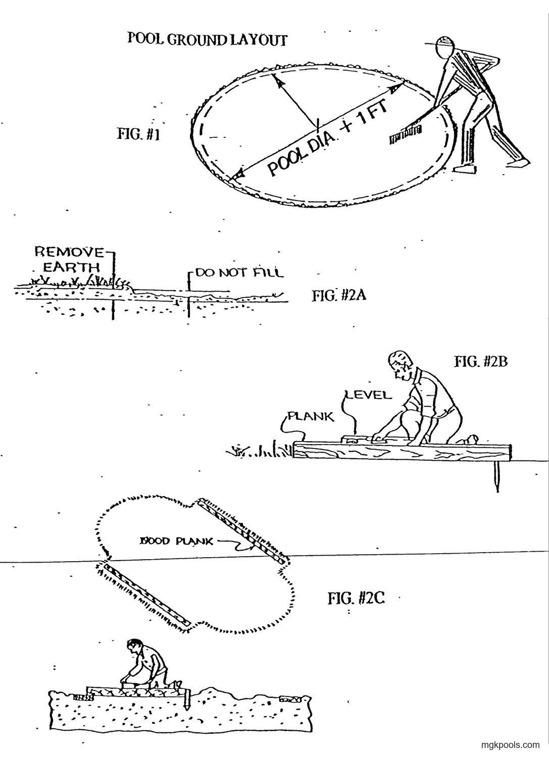
Labels printed in this drawing
- FIG. #1
- POOL DIA. + 1 FT.
Labels printed in this drawing
- REMOVE EARTH
- DO NOT FILL
- FIG. #2A
Labels printed in this drawing
- PLANK
- LEVEL
- FIG. #2B
Labels printed in this drawing
- WOOD PLANK
- FIG. #2C
ROUND BOTTOM SILL ARRANGEMENT
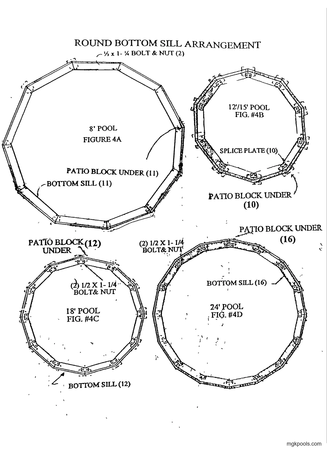
Labels printed in this drawing
- 1/2 x 1-1/4 BOLT & NUT (2)
- 8' POOL
- FIGURE 4A
- PATIO BLOCK UNDER (11)
- BOTTOM SILL (11)
Labels printed in this drawing
- 12'/15' POOL
- FIG. #4B
- SPLICE PLATE (10)
- PATIO BLOCK UNDER (10)
Labels printed in this drawing
- PATIO BLOCK UNDER (12)
- (2) 1/2 X 1-1/4 BOLT & NUT
- 18' POOL
- FIG. #4C
- BOTTOM SILL (12)
Labels printed in this drawing
- PATIO BLOCK UNDER (16)
- BOTTOM SILL (16)
- 24' POOL
- FIG. #4D
ROUND BOTTOM SILL INSTALLATION
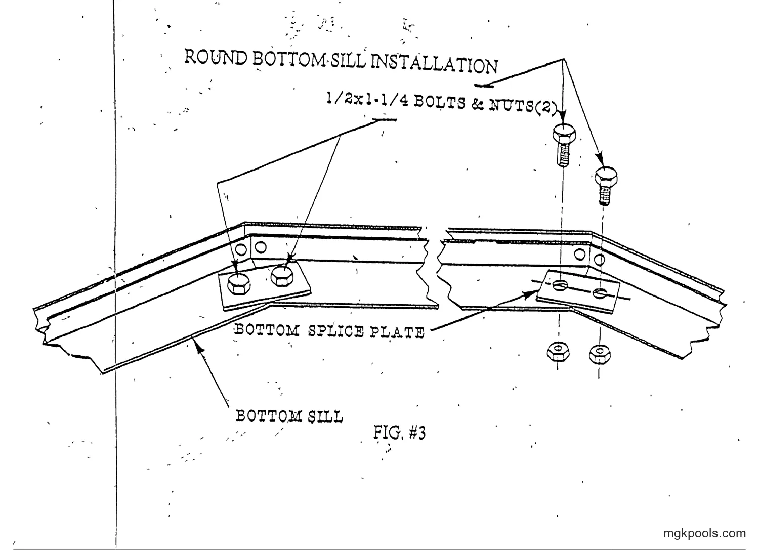
Labels printed in this drawing
- ROUND BOTTOM SILL INSTALLATION
- 1/2×1-1/4 BOLTS & NUTS (2)
- BOTTOM SPLICE PLATE
- BOTTOM SILL
- FIG. #3
OVAL BOTTOM SILL ARRANGEMENTS
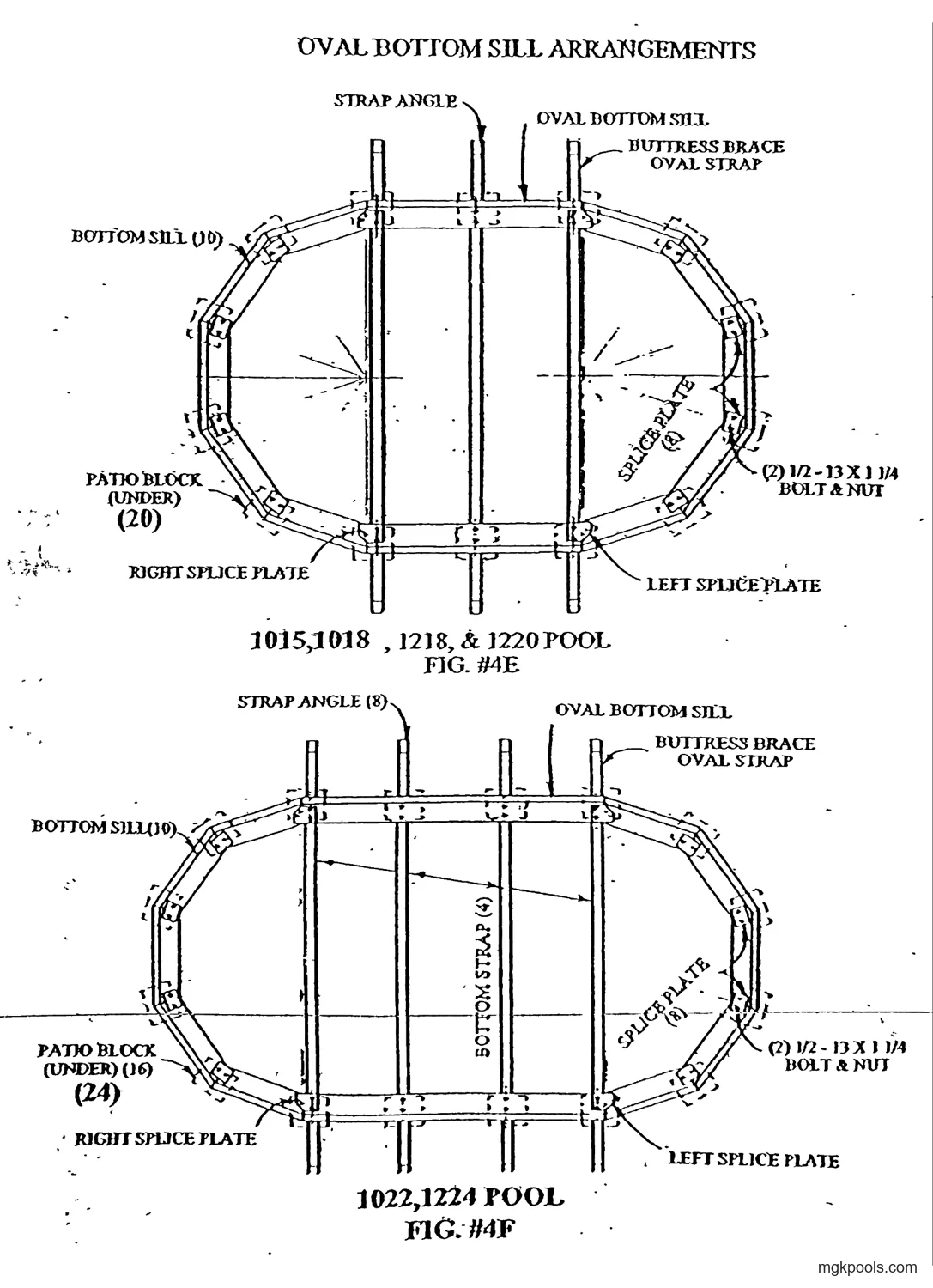
Labels printed in this drawing
- STRAP ANGLE
- OVAL BOTTOM SILL
- BUTTRESS BRACE OVAL STRAP
- BOTTOM SILL (10)
- SPLICE PLATE (4)
- (2) 1/2 – 13 X 1 1/4 BOLT & NUT
- PATIO BLOCK (UNDER) (20)
- RIGHT SPLICE PLATE
- LEFT SPLICE PLATE
- 1015,1018 , 1218, & 1220 POOL
- FIG. #4E
Labels printed in this drawing
- STRAP ANGLE (8)
- OVAL BOTTOM SILL
- BUTTRESS BRACE OVAL STRAP
- BOTTOM SILL (10)
- BOTTOM STRAP (4)
- SPLICE PLATE (8)
- (2) 1/2 – 13 X 1 1/4 BOLT & NUT
- PATIO BLOCK (UNDER) (16) (24)
- RIGHT SPLICE PLATE
- LEFT SPLICE PLATE
- 1022,1224 POOL
- FIG. #4F
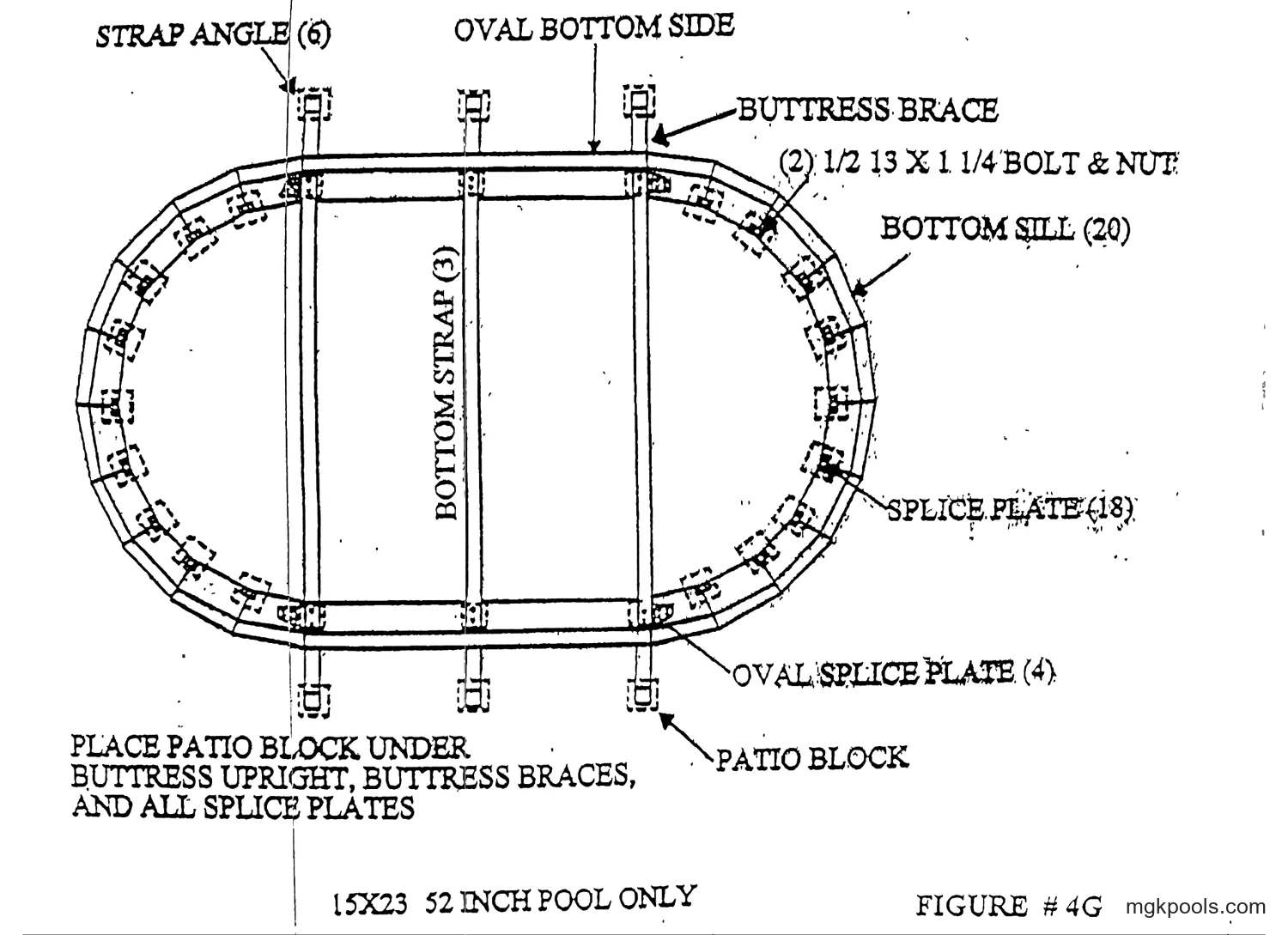
Labels printed in this drawing
- OVAL BOTTOM SIDE
- BUTTRESS BRACE
- (2) 1/2 13 X 1 1/4 BOLT & NUT
- BOTTOM SILL (20)
- SPLICE PLATE (18)
- OVAL SPLICE PLATE (4)
- PATIO BLOCK
- BOTTOM STRAP (3)
- STRAP ANGLE (6)
- PLACE PATIO BLOCK UNDER BUTTRESS UPRIGHT, BUTTRESS BRACES, AND ALL SPLICE PLATES
- 15X23 52 INCH POOL ONLY
- FIGURE #4G
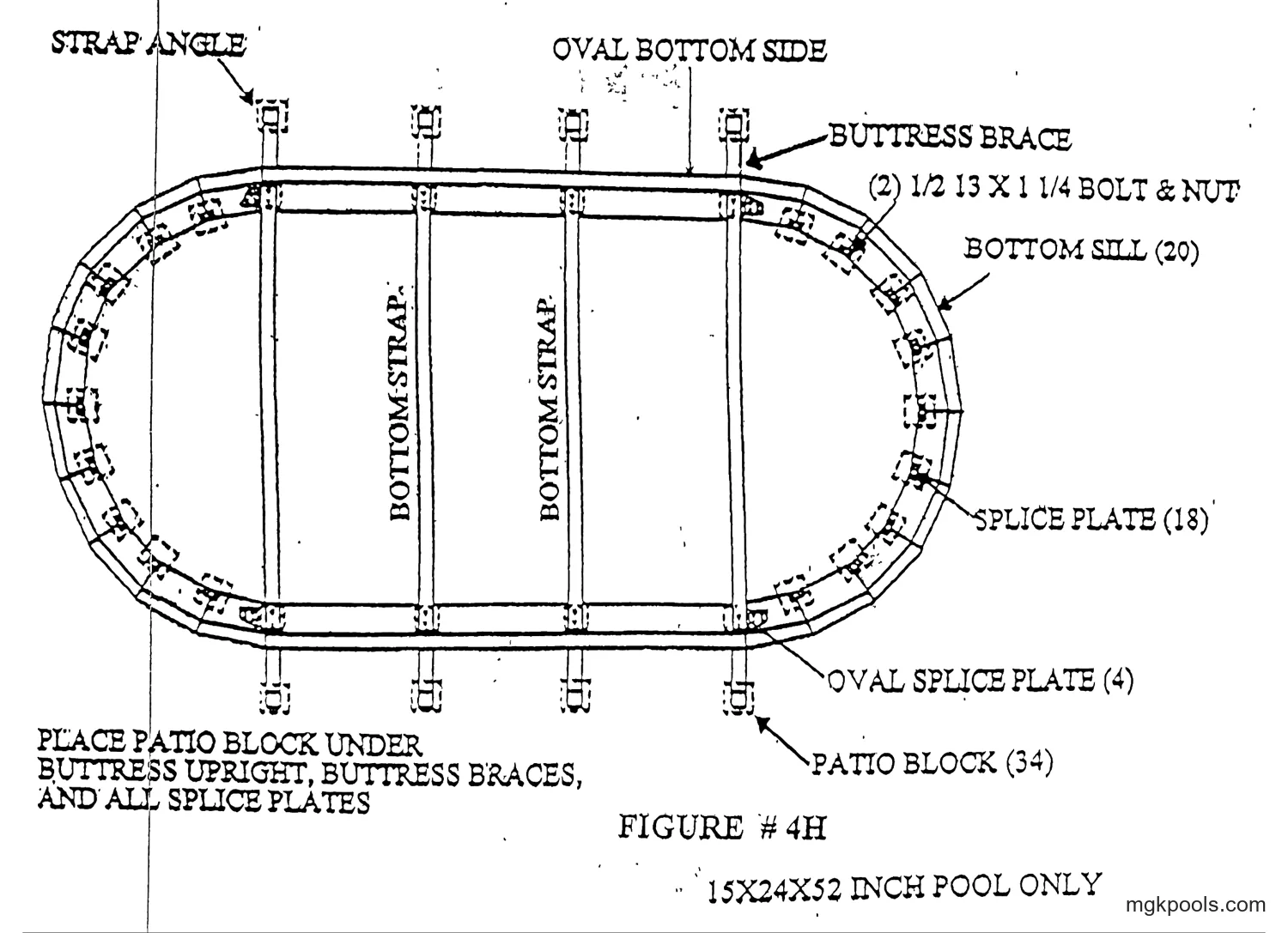
Labels printed in this drawing
- OVAL BOTTOM SIDE
- BUTTRESS BRACE
- (2) 1/2 13 X 1 1/4 BOLT & NUT
- BOTTOM SILL (20)
- SPLICE PLATE (18)
- OVAL SPLICE PLATE (4)
- PATIO BLOCK (34)
- BOTTOM STRAP
- BOTTOM STRAP
- STRAP ANGLE
- FIGURE # 4H
- 15X24X52 INCH POOL ONLY
- PLACE PATIO BLOCK UNDER BUTTRESS UPRIGHT, BUTTRESS BRACES, AND ALL SPLICE PLATES
ROUND BUTTRESS, BOTTOM SILL, SPLICE, AND BUTTRESS UPRIGHT
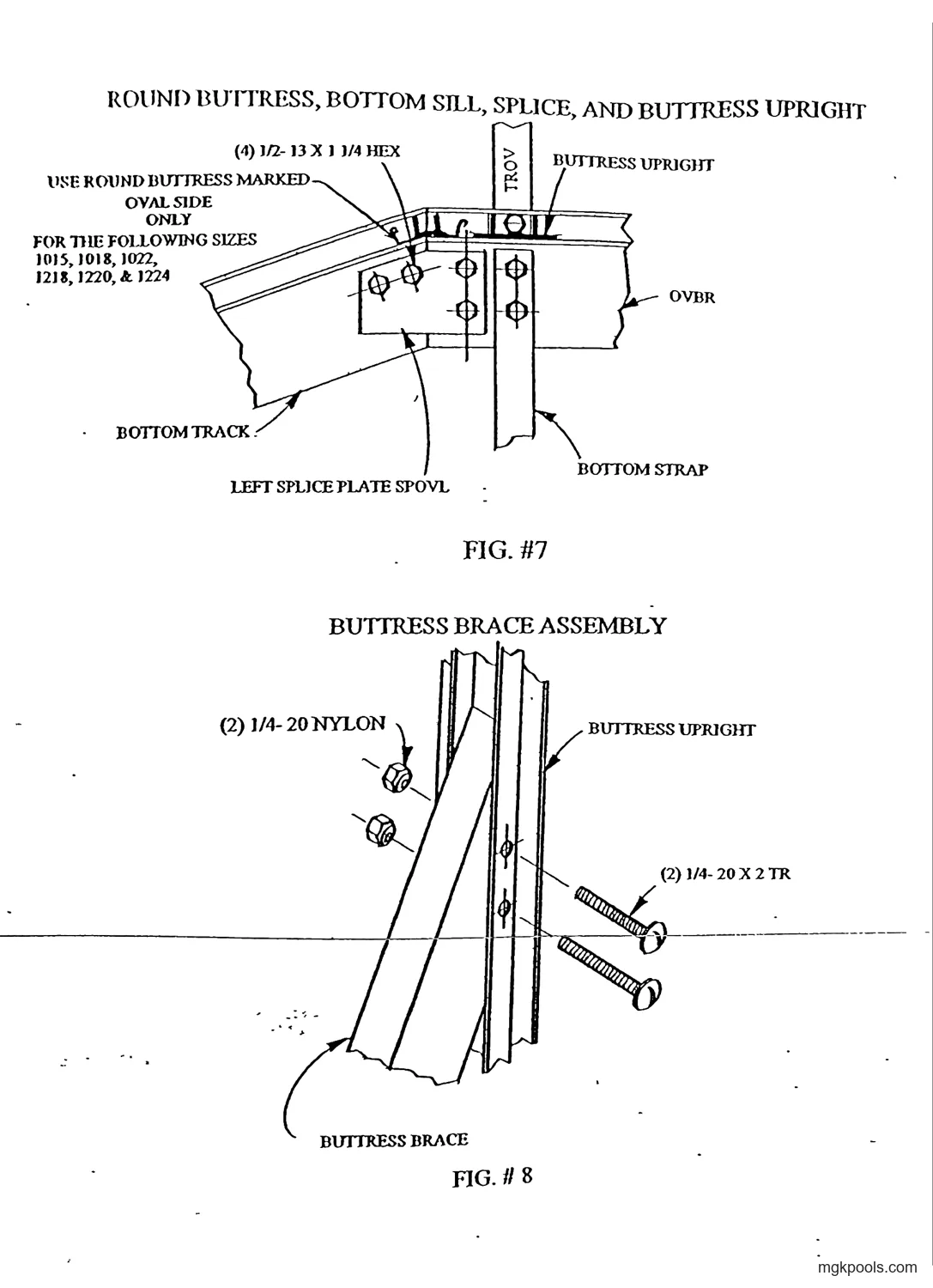
Labels printed in this drawing
- (4) 1/2-13 X 1 1/4 HEX
- TROV
- BUTTRESS UPRIGHT
- USE ROUND BUTTRESS MARKED OVAL SIDE ONLY FOR THE FOLLOWING SIZES 1015, 1018, 1022, 1218, 1220, & 1224
- OVBR
- BOTTOM TRACK
- LEFT SPLICE PLATE SPOVL
- BOTTOM STRAP
- FIG. #7
BUTTRESS BRACE ASSEMBLY
Labels printed in this drawing
- (2) 1/4-20 NYLON
- BUTTRESS UPRIGHT
- (2) 1/4-20 X 2 TR
- BUTTRESS BRACE
- FIG. # 8
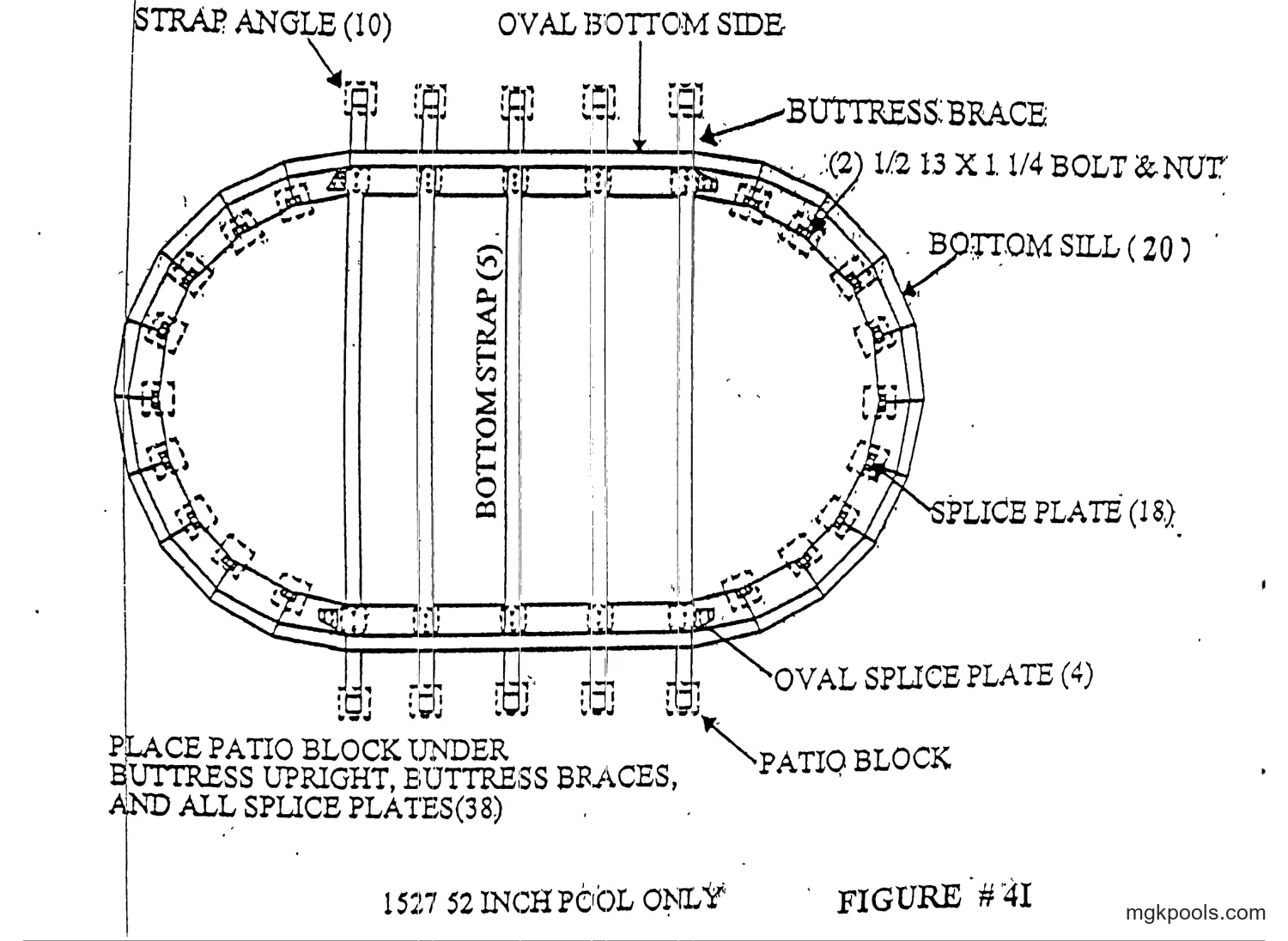
Labels printed in this drawing
- OVAL BOTTOM SIDE
- BUTTRESS BRACE
- (2) 1/2 13 X 1 1/4 BOLT & NUT
- BOTTOM SILL ( 20 )
- SPLICE PLATE (18)
- OVAL SPLICE PLATE (4)
- PATIO BLOCK
- FIGURE # 4I
- 1527 52 INCH POOL ONLY
- BOTTOM STRAP (5)
- STRAP ANGLE (10)
- PLACE PATIO BLOCK UNDER BUTTRESS UPRIGHT, BUTTRESS BRACES, AND ALL SPLICE PLATES (38)
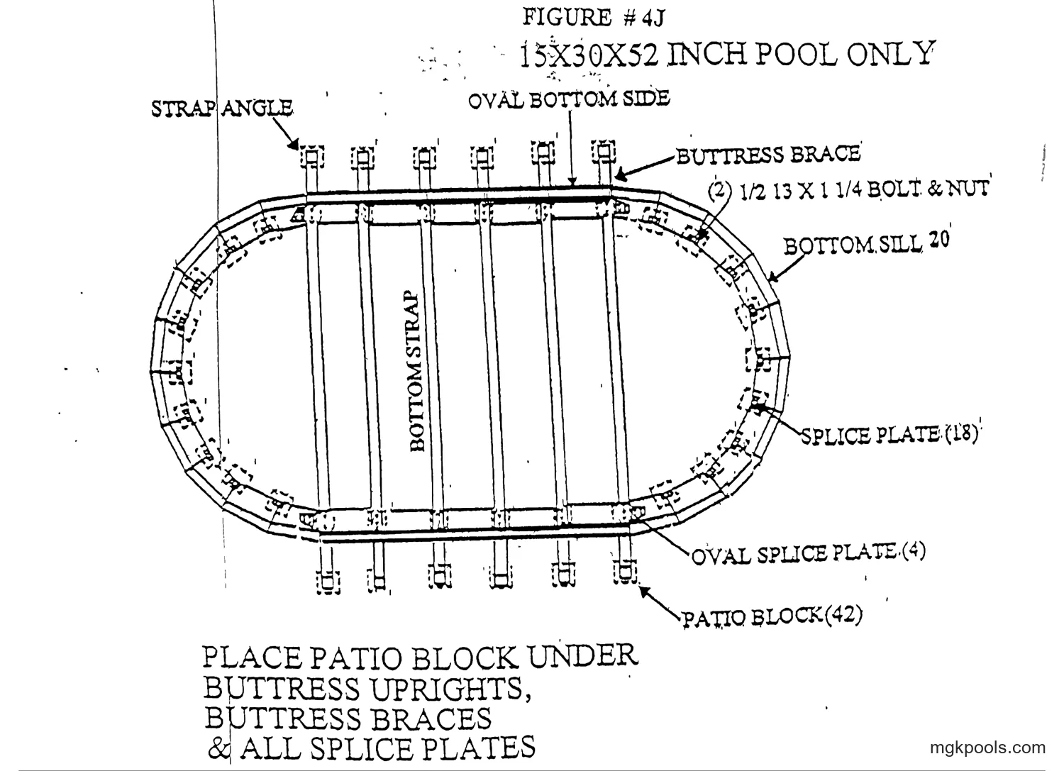
Labels printed in this drawing
- FIGURE # 4J
- 15X30X52 INCH POOL ONLY
- OVAL BOTTOM SIDE
- BUTTRESS BRACE
- (2) 1/2 13 X 1 1/4 BOLT & NUT
- BOTTOM SILL 20
- SPLICE PLATE (18)
- OVAL SPLICE PLATE (4)
- PATIO BLOCK (42)
- BOTTOM STRAP
- STRAP ANGLE
- PLACE PATIO BLOCK UNDER BUTTRESS UPRIGHTS, BUTTRESS BRACES & ALL SPLICE PLATES
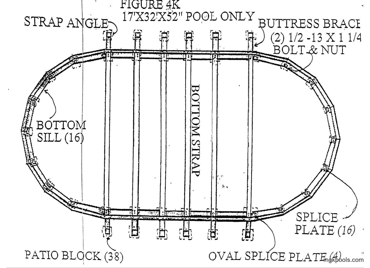
Labels printed in this drawing
- FIGURE 4K
- 17'X32'X52" POOL ONLY
- BUTTRESS BRACE
- (2) 1/2 -13 X 1 1/4 BOLT & NUT
- SPLICE PLATE (16)
- OVAL SPLICE PLATE (4)
- BOTTOM STRAP
- STRAP ANGLE
- BOTTOM SILL (16)
- PATIO BLOCK (38)
PREASSEMBLY OF STRAP ANGLE, CLIP, AND OVAL BOTTOM RAIL
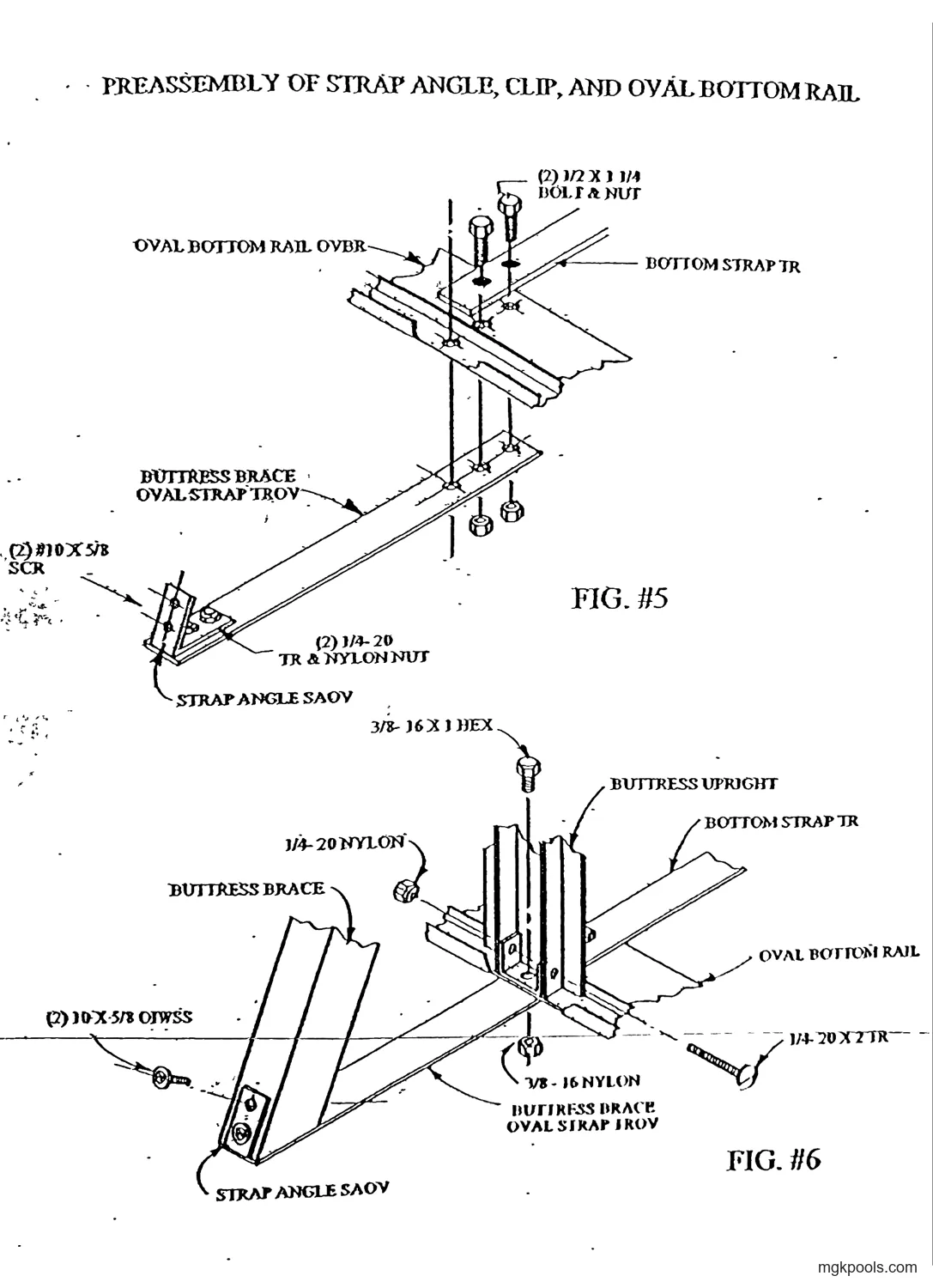
Labels printed in this drawing
- (2) 1/2 X 1 1/4 BOLT & NUT
- OVAL BOTTOM RAIL OVBR
- BOTTOM STRAP TR
- BUTTRESS BRACE OVAL STRAP TROV
- (2) #10 X 5/8 SCR
- (2) 1/4-20 TR & NYLON NUT
- STRAP ANGLE SAOV
- FIG. #5
Labels printed in this drawing
- 3/8-16 X 1 HEX
- BUTTRESS UPRIGHT
- BOTTOM STRAP TR
- 1/4-20 NYLON
- BUTTRESS BRACE
- OVAL BOTTOM RAIL
- (2) 10 X 5/8 OIWSS
- 1/4-20 X 2 TR
- 3/8 – 16 NYLON
- BUTTRESS BRACE OVAL STRAP TROV
- STRAP ANGLE SAOV
- FIG. #6
WALL PANEL & BUTTRESS UPRIGHT ASSEMBLY
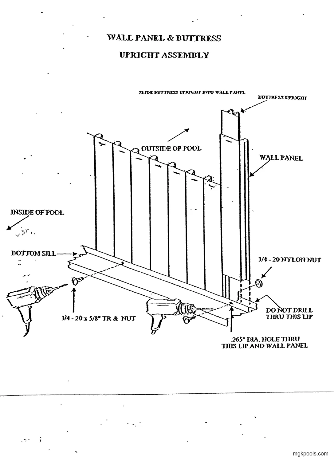
Labels printed in this drawing
- SLIDE BUTTRESS UPRIGHT INTO WALL PANEL
- BUTTRESS UPRIGHT
- OUTSIDE OF POOL
- WALL PANEL
- INSIDE OF POOL
- BOTTOM SILL
- 1/4 – 20 NYLON NUT
- 1/4 – 20 x 5/8" TR & NUT
- DO NOT DRILL THRU THIS LIP
- .265" DIA. HOLE THRU THIS LIP AND WALL PANEL
ROUND BUTTRESS UPRIGHT ASSEMBLY
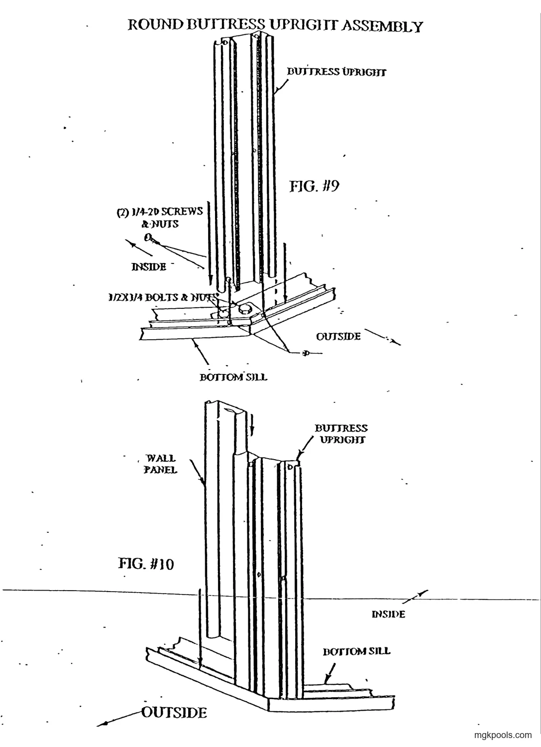
Labels printed in this drawing
- BUTTRESS UPRIGHT
- FIG. #9
- (2) 1/4-20 SCREWS & NUTS
- INSIDE
- 1/2X1/4 BOLTS & NUTS
- OUTSIDE
- BOTTOM SILL
Labels printed in this drawing
- WALL PANEL
- BUTTRESS UPRIGHT
- FIG. #10
- INSIDE
- BOTTOM SILL
- OUTSIDE
CONNECTING TOP RAIL ASSEMBLY
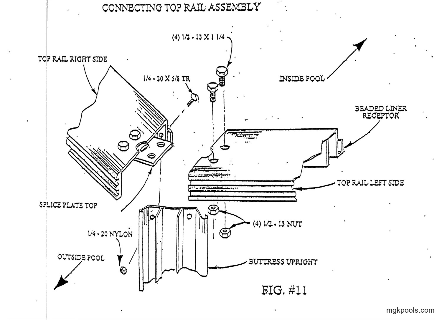
Labels printed in this drawing
- INSIDE POOL
- BEADED LINER RECEPTOR
- TOP RAIL LEFT SIDE
- (4) 1/2 – 13 X 1 1/4
- (4) 1/2 – 13 NUT
- BUTTRESS UPRIGHT
- FIG. # 11
- 1/4 – 20 X 5/8 TR
- TOP RAIL RIGHT SIDE
- SPLICE PLATE TOP
- 1/4 – 20 NYLON
- OUTSIDE POOL
HOLD DOWN SHEETS FOR OVALS ONLY
Add Hold Down Sheets and Fasten to the sill on straight side of oval with 1/4-20X5/8 Screw and Nut. When installing Hold Down Sheets, Overlap consecutive Sheets 5″.
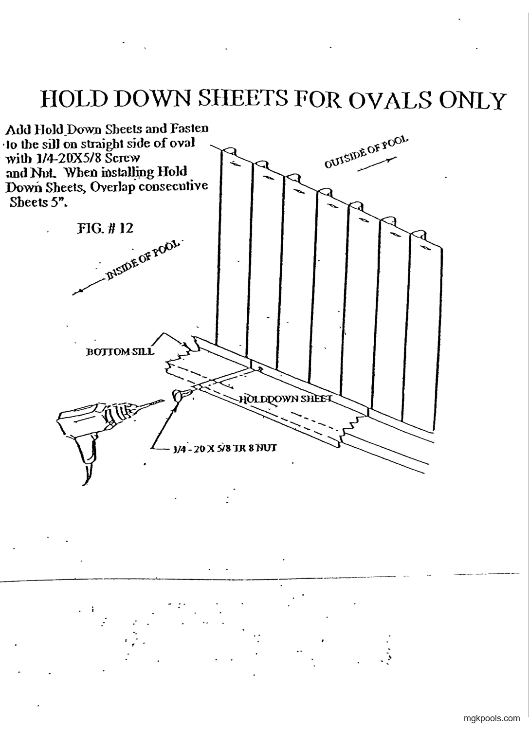
Labels printed in this drawing
- FIG. # 12
- OUTSIDE OF POOL
- INSIDE OF POOL
- BOTTOM SILL
- HOLDDOWN SHEET
- 1/4 – 20 X 5/8 TR & NUT
COMPLETED TOPRAIL AND WALL PANEL CONNECTION.
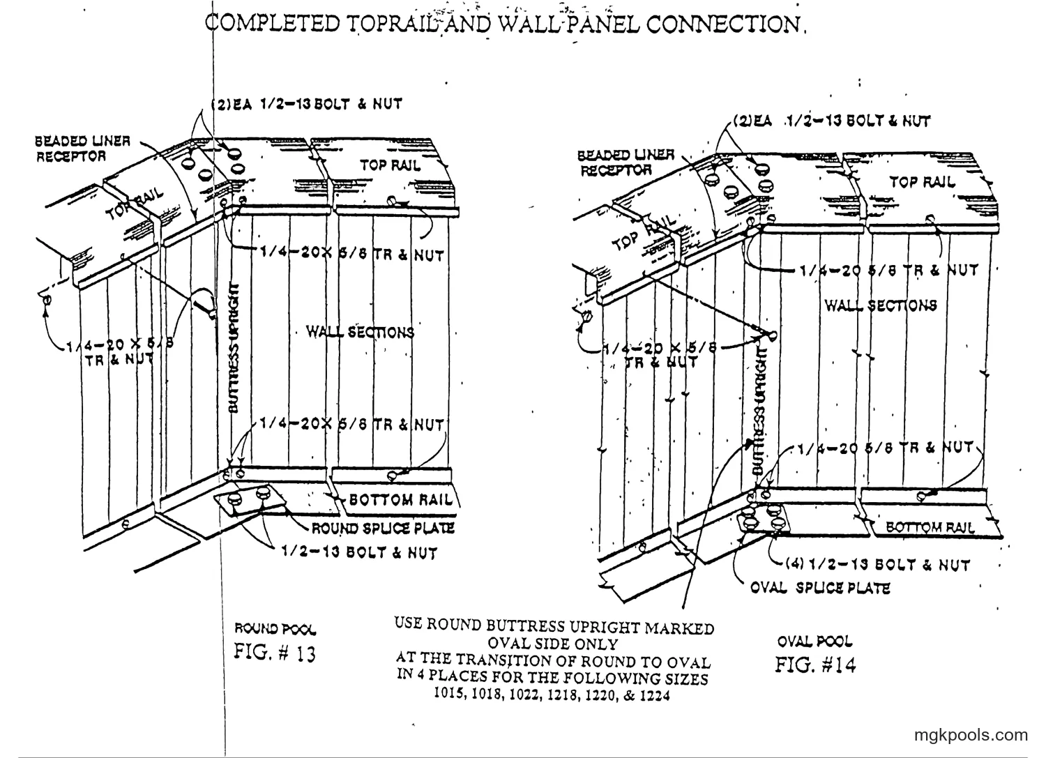
Labels printed in this drawing
- BEADED LINER RECEPTOR
- TOP RAIL
- (2)EA 1/2-13 BOLT & NUT
- TOP RAIL
- 1/4-20 X 5/8 TR & NUT
- WALL SECTIONS
- BUTTRESS UPRIGHT
- 1/4-20 X 5/8 TR & NUT
- 1/4-20 X 5/8 TR & NUT
- BOTTOM RAIL
- ROUND SPLICE PLATE
- 1/2-13 BOLT & NUT
- ROUND POOL
- FIG. # 13
Labels printed in this drawing
- BEADED LINER RECEPTOR
- TOP RAIL
- (2)EA 1/2-13 BOLT & NUT
- TOP RAIL
- 1/4-20 X 5/8 TR & NUT
- WALL SECTIONS
- BUTTRESS UPRIGHT
- 1/4-20 X 5/8 TR & NUT
- 1/4-20 X 5/8 TR & NUT
- BOTTOM RAIL
- (4) 1/2-13 BOLT & NUT
- OVAL SPLICE PLATE
- OVAL POOL
- FIG. #14
USE ROUND BUTTRESS UPRIGHT MARKED OVAL SIDE ONLY AT THE TRANSITION OF ROUND TO OVAL IN 4 PLACES FOR THE FOLLOWING SIZES 1015, 1018, 1022, 1218, 1220, & 1224
COMPLETED CAP SET AND TOP RAIL ASSEMBLY
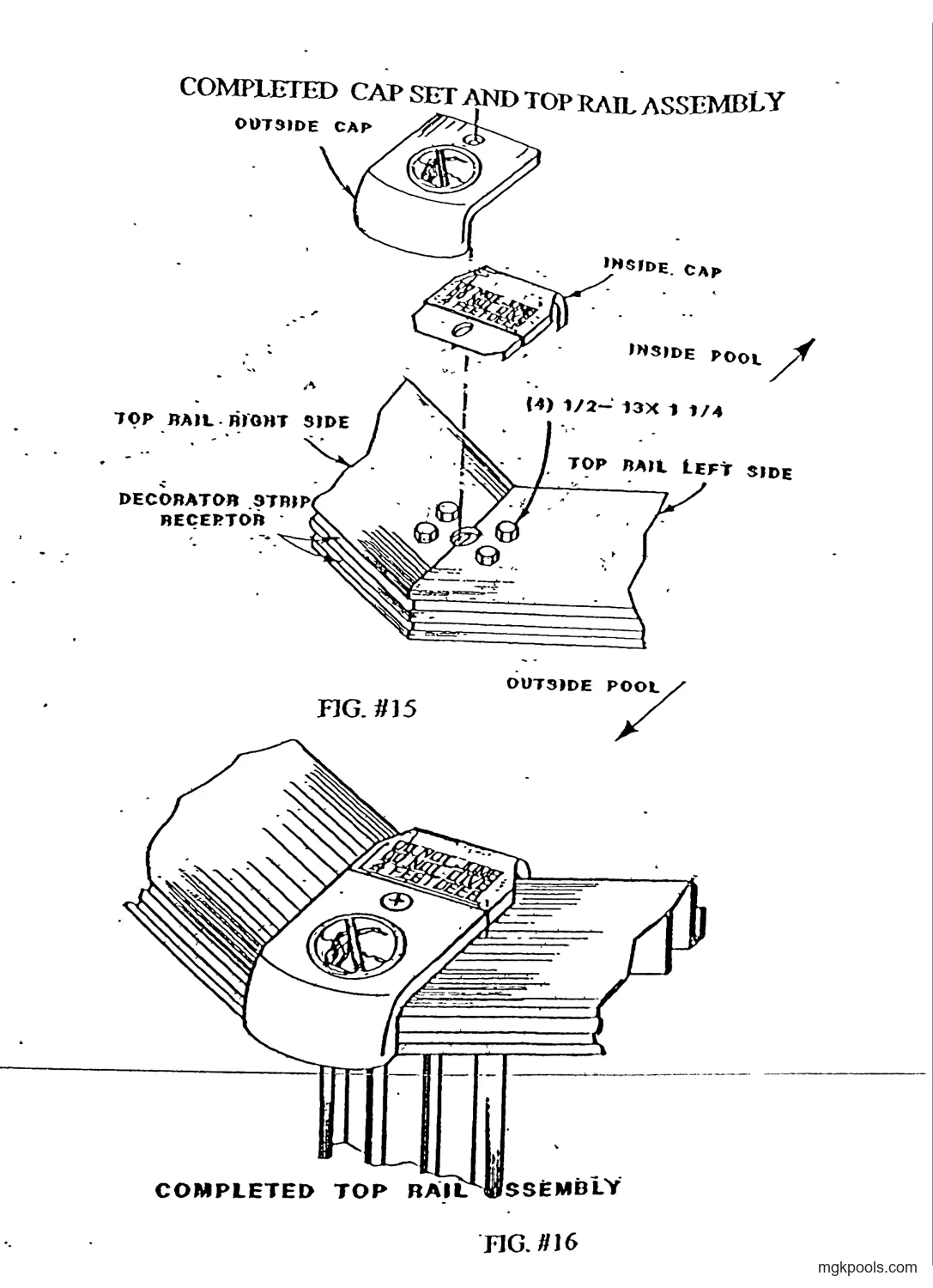
Labels printed in this drawing
- OUTSIDE CAP
- INSIDE CAP
- INSIDE POOL (arrow)
- TOP RAIL RIGHT SIDE
- (4) 1/2-13 X 1 1/4
- TOP RAIL LEFT SIDE
- DECORATOR STRIP RECEPTOR
- OUTSIDE POOL (arrow)
- FIG. #15
- (small printed label on the face of the inside cap: [illegible])
Labels printed in this drawing
- COMPLETED TOP RAIL ASSEMBLY
- FIG. #16
ATTACHMENT OF SUPPORT BRACKET FOR 52″
15X23, 15X24 15X27, 15X30 17X32 15′, 18′, 21′, & 24′ ONLY
FIG. #17
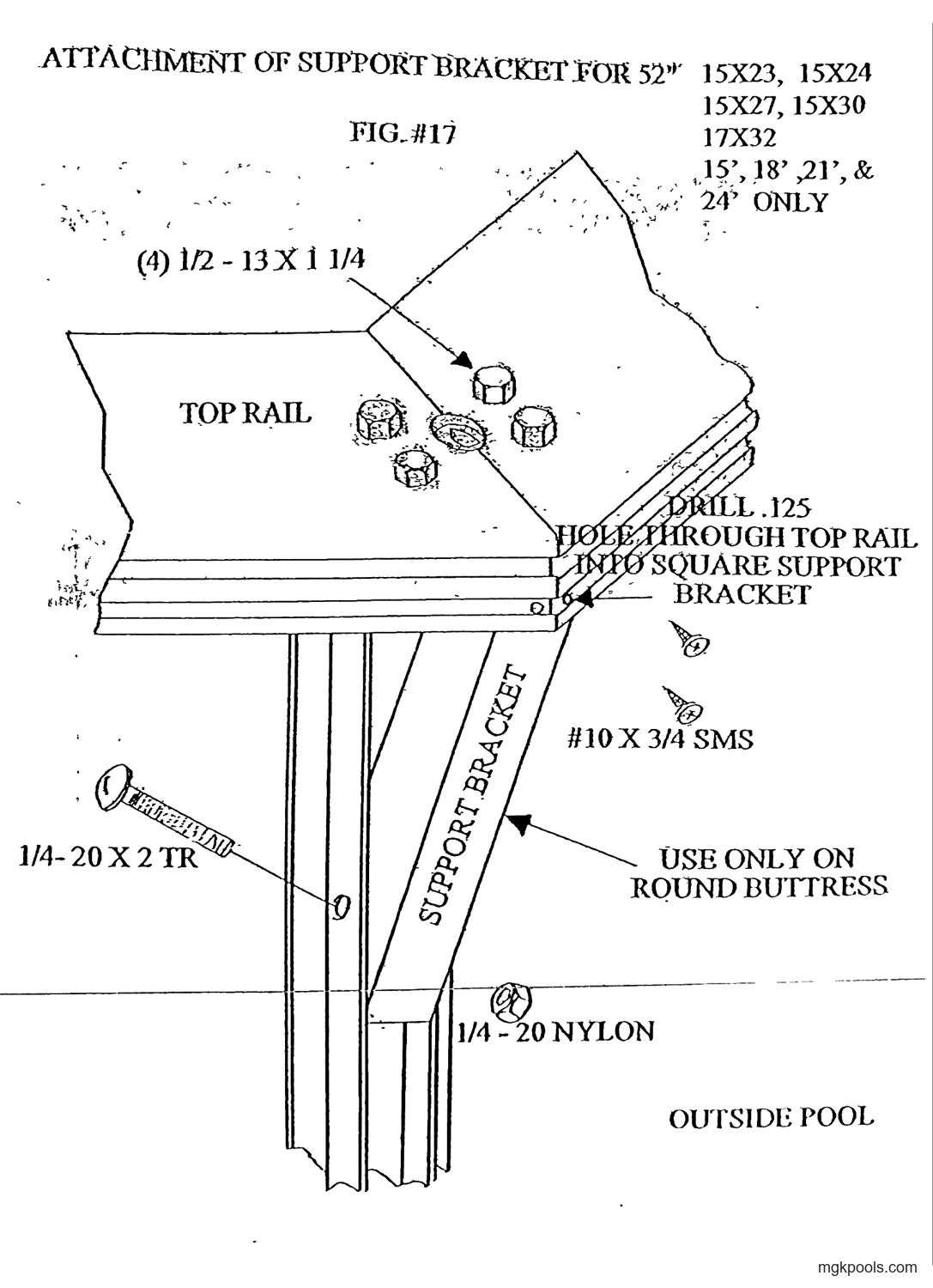
Labels printed in this drawing
- (4) 1/2 – 13 X 1 1/4
- TOP RAIL
- DRILL .125 HOLE THROUGH TOP RAIL INTO SQUARE SUPPORT BRACKET
- #10 X 3/4 SMS
- 1/4-20 X 2 TR
- SUPPORT BRACKET
- USE ONLY ON ROUND BUTTRESS
- 1/4 – 20 NYLON
- OUTSIDE POOL
Build photos and videos
Web edition by MGK Pools, Winchendon, Massachusetts. Source: https://mgkpools.com/aquasport-52/owners-manual/
Videos
 Play
 Play
 Play
 Play
 Play
Advisories I to VII: warnings and safety labels
Web edition by MGK Pools, Winchendon, Massachusetts. Source: https://mgkpools.com/aquasport-52/owners-manual/
ADVISORY I
WARNING
According to current National Spa and Pool Institute minimum standards for residential pools, your ABOVE GROUND/ ON GROUND POOL is classified as a Non-Diving Pool (Type O or Non-Conforming).
For your safety, read all information included in this packet before using your pool to avoid neck and head injury.
It is the:
POOL OWNER’S LEGAL RESPONSIBILITY
1) to WARN all users of the hazards of a pool, 2) to ENFORCE all safety rules, and 3) to MAINTAIN the pool and CORRECT any hazardous conditions.
You are responsible for informing all pool users of the enclosed information
-Understand it -Communicate it -Enforce it
ADVISORY II
CAUTION
ABOVE GROUND POOLS ARE DESIGNED FOR WADING AND SWIMMING
JUMPING, SLIDING OR DIVING MAY CAUSE SEVERE INJURIES
PRODUCT SAFETY IS THE JOINT RESPONSIBILITY OF THE MANUFACTURER AND END USER (CONSUMER)
Change of Design: The company expressly reserves the right to change or modify the design and construction of any product in due course of our manufacturing procedures, without incurring any obligation or liability to furnish or install such changes or modifications on products previously or subsequently sold.
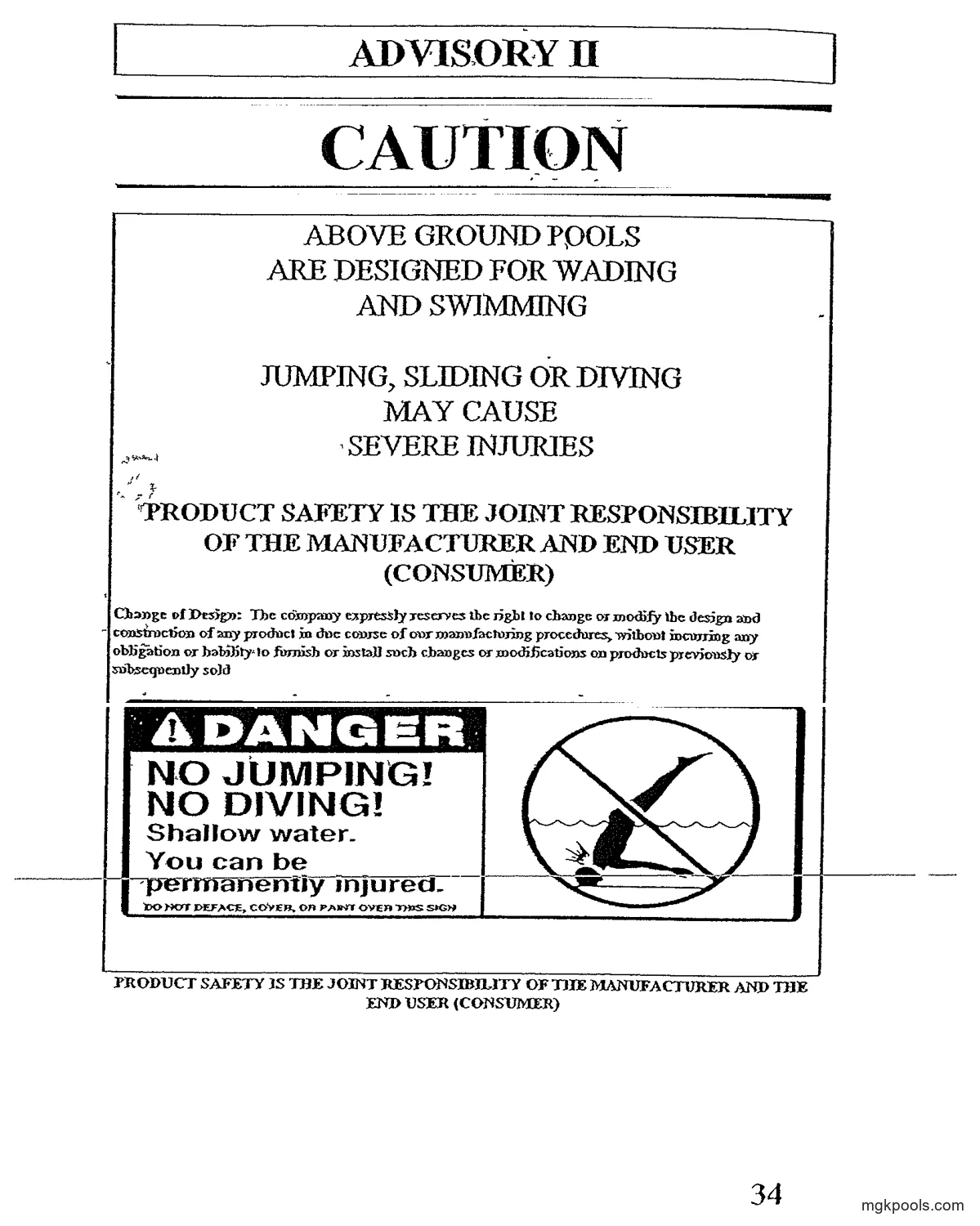
Labels printed in this drawing
- DANGER
- NO JUMPING!
- NO DIVING!
- Shallow water.
- You can be permanently injured.
- DO NOT DEFACE, COVER, OR PAINT OVER THIS SIGN
PRODUCT SAFETY IS THE JOINT RESPONSIBILITY OF THE MANUFACTURER AND THE END USER (CONSUMER)
ADVISORY III
INSTALLATION INSTRUCTIONS SAFETY FIRST LABELS
THINK SAFETY FIRST. . .AND SHARE YOUR WISDOM
CAUTION: THESE POOLS ARE DESIGNED FOR SWIMMING ONLY THEY ARE NOT DESIGNED FOR DIVING, SLIDING OR JUMPING. DO NOT STAND OR WALK ON TOP RAIL.
INSTALL SAFETY LABEL ON WALL AND LINER. Your new pool liner is designed for safe use by you, your family and friends. Do not MIS-USE the product by jumping or diving into the water.
JUMPING, SLIDING, OR DIVING MIS-USE! The product is designed for swimming and for wading only.
If you jump into the water, you could seriously injure your back, neck, or hurt others. If you dive into the water, you could hit your head on the bottom. If you do, you could be paralyzed permanently from the neck down for the rest of your life.
We tell you this for a good reason: A number of people who chose to dive are now paralyzed. And the facts show that many of these were experienced divers! WE DON’T WANT THIS TO HAPPEN TO YOU. DON’T JUMP, SLIDE OR DIVE!
Install the safety labels we have provided. Follow the steps in the instruction manual.
Installation Guide. Inform family and friends about correct use of the product for safe pool enjoyment.
Think SAFETY FIRST….and share your wisdom!
PROTECT THE GOOD HEALTH OF YOUR FAMILY AND FRIENDS. Placement of safety labels on the pool wall and pool liner is mandatory.
Peel off the backing and attach two (2) labels on a DRY liner so that the bottom edge of the label is no more than 4″ below the top rail of the pool. Position as shown in the illustration in ADVISORY V. Place the other two labels on outside of the pool wall as shown.
Failure to comply with all caution signs and all pool safety rules may result in serious permanent body injury.
Write in number of liner model from outside of carton for future reference. Write in warranty card number.
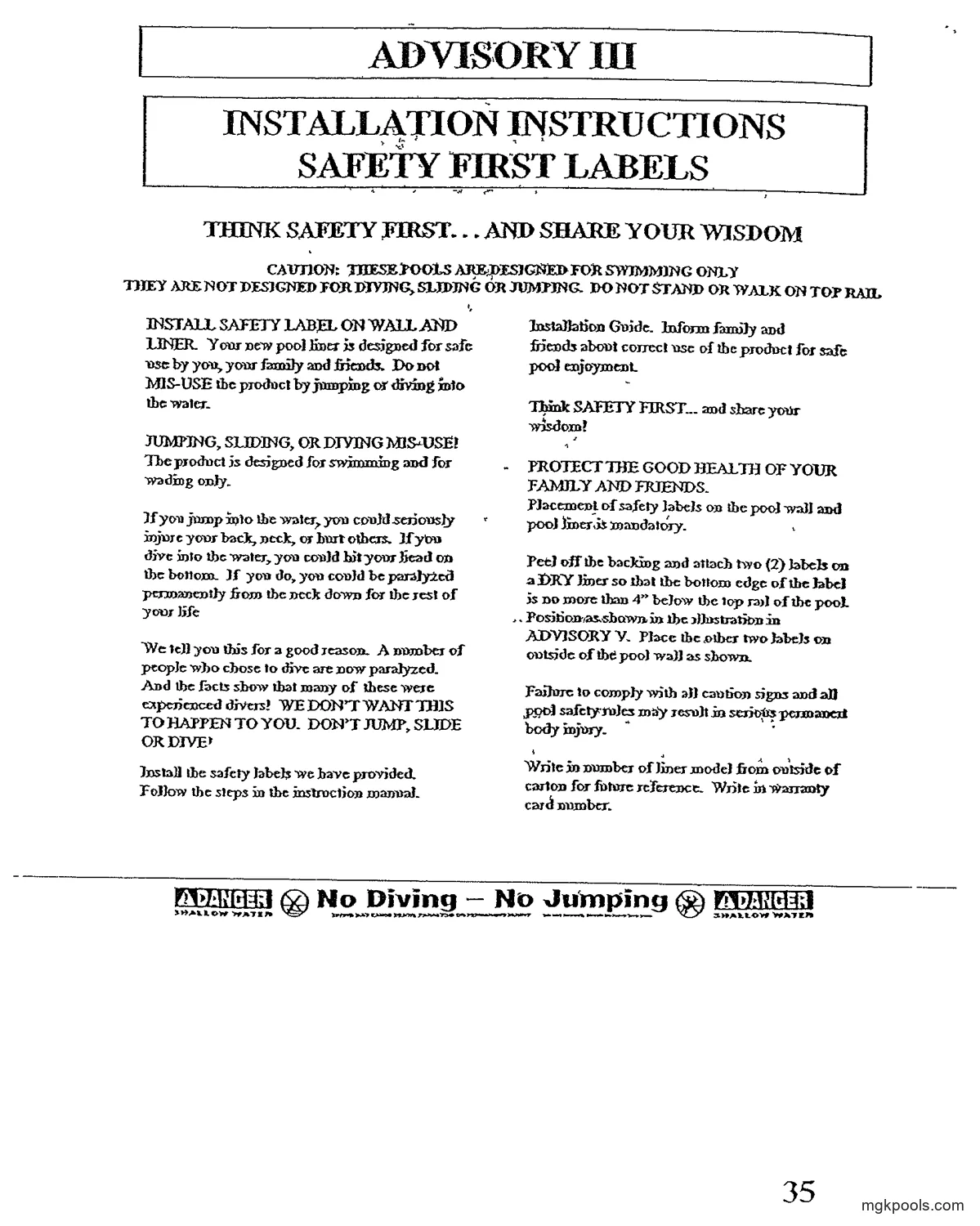
Labels printed in this drawing
- DANGER
- SHALLOW WATER
- No Diving – No Jumping
- DANGER
- SHALLOW WATER
- (two lines of fine print under the words: [illegible])
ADVISORY IV
INSTRUCTIONS FOR PROPER APPLICATION OF
“DANGER–NO JUMPING NO DIVING” LABELS
BY DEALER/INSTALLER/POOL OWNER
TO
VINYL LINERS
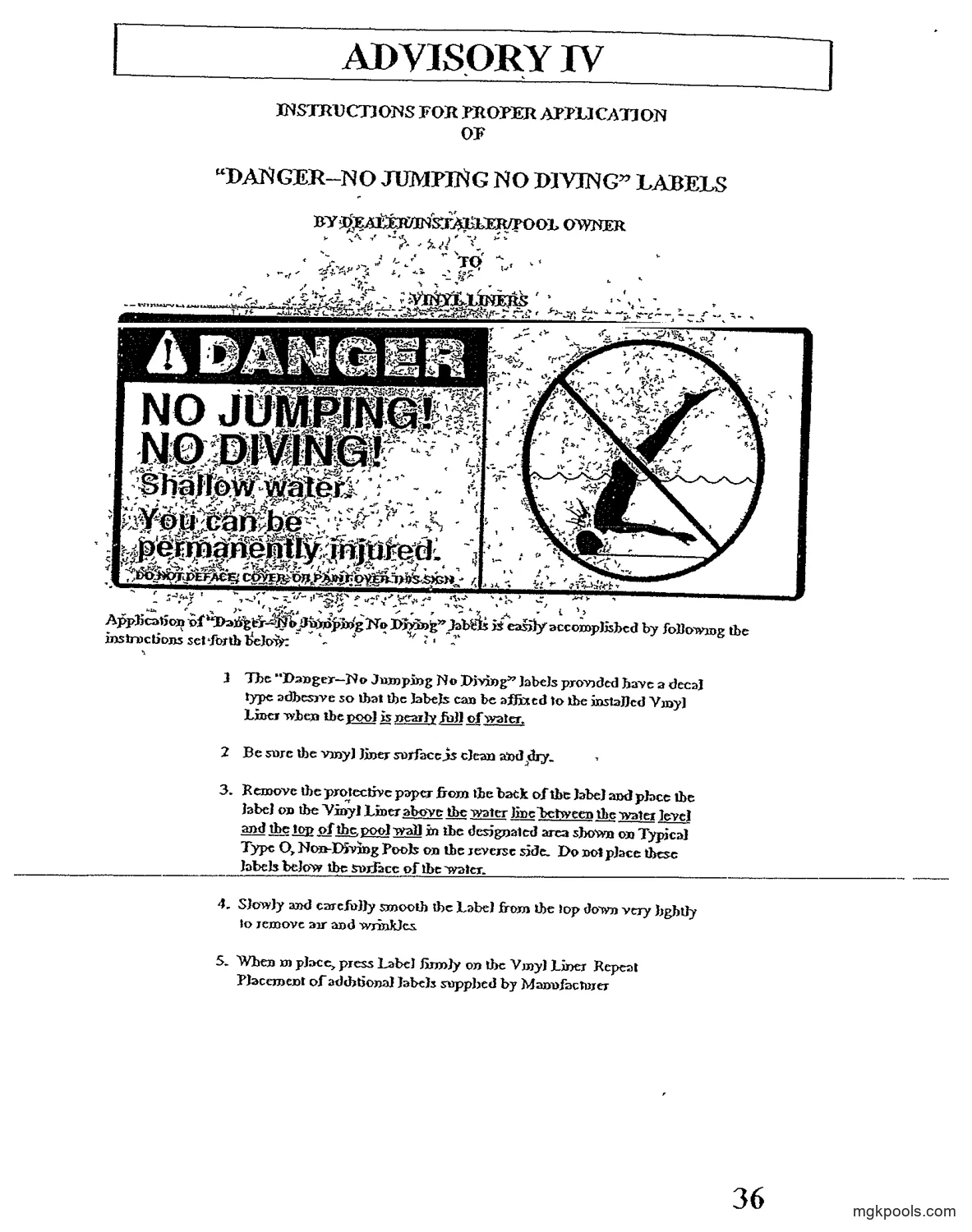
Labels printed in this drawing
- DANGER
- NO JUMPING!
- NO DIVING!
- Shallow water.
- You can be permanently injured.
- DO NOT DEFACE, COVER, OR PAINT OVER THIS SIGN
Application of “Danger–No Jumping No Diving” labels is easily accomplished by following the instructions set forth below:
-
The “Danger–No Jumping No Diving” labels provided have a decal type adhesive so that the labels can be affixed to the installed Vinyl Liner when the pool is nearly full of water.
-
Be sure the vinyl liner surface is clean and dry.
-
Remove the protective paper from the back of the label and place the label on the Vinyl Liner above the water line between the water level and the top of the pool wall in the designated area shown on Typical Type O, Non-Diving Pools on the reverse side. Do not place these labels below the surface of the water.
-
Slowly and carefully smooth the Label from the top down very lightly to remove air and wrinkles.
-
When in place, press Label firmly on the Vinyl Liner. Repeat Placement of additional labels supplied by Manufacturer.
ADVISORY V
POSITION LABELS AS SHOWN BELOW
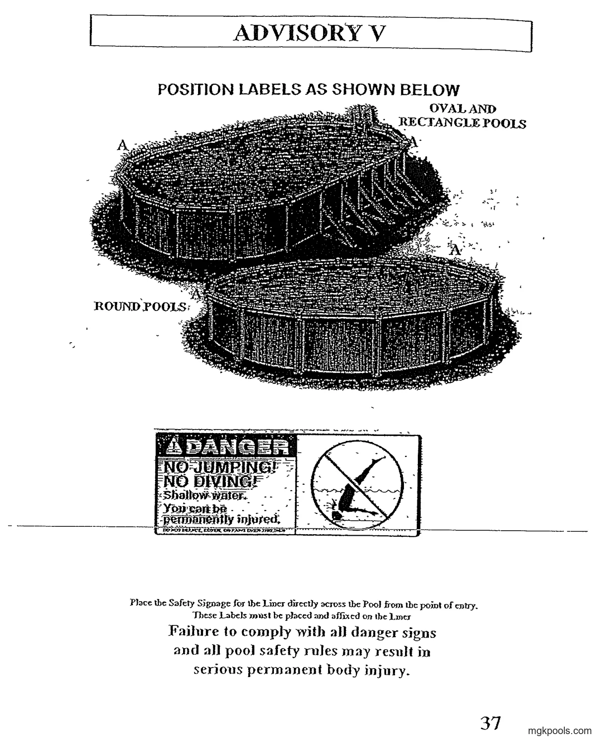
Labels printed in this drawing
- OVAL AND RECTANGLE POOLS
- A
- A
- ROUND POOLS
- A
- A
Labels printed in this drawing
- DANGER
- NO JUMPING!
- NO DIVING!
- Shallow water.
- You can be permanently injured.
- DO NOT DEFACE, COVER, OR PAINT OVER THIS SIGN
Place the Safety Signage for the Liner directly across the Pool from the point of entry. These Labels must be placed and affixed on the Liner.
Failure to comply with all danger signs and all pool safety rules may result in serious permanent body injury.
ADVISORY VI
CAUTION: ALL POOL USERS SIGN SUPPLIED WITH EVERY POOL
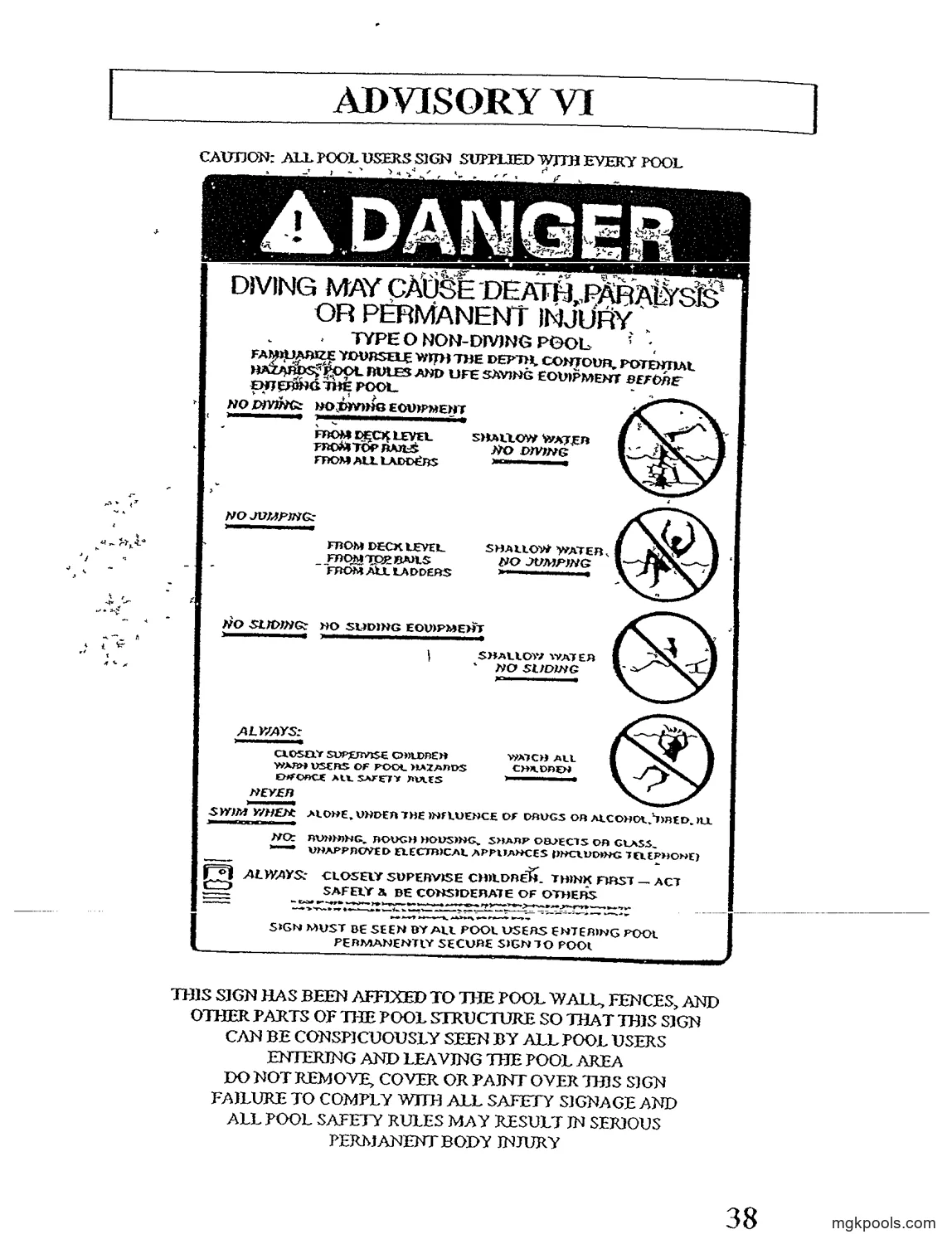
Labels printed in this drawing
- DANGER
- DIVING MAY CAUSE DEATH, PARALYSIS OR PERMANENT INJURY
- TYPE O NON-DIVING POOL
- FAMILIARIZE YOURSELF WITH THE DEPTH, CONTOUR, POTENTIAL HAZARDS, POOL RULES AND LIFE SAVING EQUIPMENT BEFORE ENTERING THE POOL.
- NO DIVING: NO DIVING EQUIPMENT
- FROM DECK LEVEL
- FROM TOP RAILS
- FROM ALL LADDERS
- SHALLOW WATER NO DIVING
- NO JUMPING:
- FROM DECK LEVEL
- FROM TOP RAILS
- FROM ALL LADDERS
- SHALLOW WATER NO JUMPING
- NO SLIDING: NO SLIDING EQUIPMENT
- SHALLOW WATER NO SLIDING
- ALWAYS:
- CLOSELY SUPERVISE CHILDREN
- WARN USERS OF POOL HAZARDS
- ENFORCE ALL SAFETY RULES
- WATCH ALL CHILDREN
- NEVER SWIM WHEN: ALONE, UNDER THE INFLUENCE OF DRUGS OR ALCOHOL, TIRED, ILL
- NO: RUNNING, ROUGH HOUSING, SHARP OBJECTS OR GLASS, UNAPPROVED ELECTRICAL APPLIANCES (INCLUDING TELEPHONE)
- ALWAYS: CLOSELY SUPERVISE CHILDREN. THINK FIRST — ACT SAFELY & BE CONSIDERATE OF OTHERS
- (three lines of fine print beneath: [illegible])
- SIGN MUST BE SEEN BY ALL POOL USERS ENTERING POOL.
- PERMANENTLY SECURE SIGN TO POOL.
THIS SIGN HAS BEEN AFFIXED TO THE POOL WALL, FENCES, AND OTHER PARTS OF THE POOL STRUCTURE SO THAT THIS SIGN CAN BE CONSPICUOUSLY SEEN BY ALL POOL USERS ENTERING AND LEAVING THE POOL AREA DO NOT REMOVE, COVER OR PAINT OVER THIS SIGN FAILURE TO COMPLY WITH ALL SAFETY SIGNAGE AND ALL POOL SAFETY RULES MAY RESULT IN SERIOUS PERMANENT BODY INJURY
ADVISORY VII
FACTORY AFFIXED LABELS
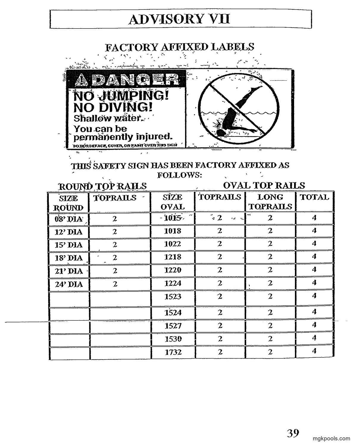
Labels printed in this drawing
- DANGER
- NO JUMPING!
- NO DIVING!
- Shallow water.
- You can be permanently injured.
- DO NOT DEFACE, COVER, OR PAINT OVER THIS SIGN
THIS SAFETY SIGN HAS BEEN FACTORY AFFIXED AS FOLLOWS:
ROUND TOP RAILS / OVAL TOP RAILS
| SIZE ROUND | TOPRAILS | SIZE OVAL | TOPRAILS | LONG TOPRAILS | TOTAL |
|---|---|---|---|---|---|
| 08′ DIA | 2 | 1015 | 2 | 2 | 4 |
| 12′ DIA | 2 | 1018 | 2 | 2 | 4 |
| 15′ DIA | 2 | 1022 | 2 | 2 | 4 |
| 18′ DIA | 2 | 1218 | 2 | 2 | 4 |
| 21′ DIA | 2 | 1220 | 2 | 2 | 4 |
| 24′ DIA | 2 | 1224 | 2 | 2 | 4 |
| 1523 | 2 | 2 | 4 | ||
| 1524 | 2 | 2 | 4 | ||
| 1527 | 2 | 2 | 4 | ||
| 1530 | 2 | 2 | 4 | ||
| 1732 | 2 | 2 | 4 |
Advisories VIII to XIV: safety tips, chemicals, check list, decks and the barrier code
Web edition by MGK Pools, Winchendon, Massachusetts. Source: https://mgkpools.com/aquasport-52/owners-manual/
ADVISORY VIII
SAFETY TIPS FOR ALL POOL USERS
FOLLOW ALL BUILDING CODES AND STANDARDS AS THEY PERTAIN TO RESIDENTIAL POOLS. NEVER USE IMPROPERLY SIZED, INSTALLED OR MAINTAINED ACCESSORIES. BE SURE ALL SAFETY SIGNS AND DECALS ARE PROPERLY INSTALLED. CAREFULLY READ AND UNDERSTAND ALL SAFETY MATERIAL PROVIDED AND COMMUNICATE THIS INFORMATION TO ALL POOL USERS AND SUBSEQUENT OWNERS.
- ADULT SUPERVISION IS REQUIRED AT ALL TIMES
- PROVIDE MEANS OF INGRESS AND EGRESS FROM POOL BY MEANS OF LADDERS/STAIRCASES/STEPS ETC
- ENFORCE ALL RULES
- ALLOW NO DIVING
- ALLOW NO JUMPING
- ALLOW NO SLIDING
- ALLOW ONLY COMPETENT SWIMMERS IN THE POOL
- NO RUNNING OR HORSEPLAY
- SUPERVISE CHILDREN CLOSELY. SEE THAT THEY LEARN TO SWIM.
- NO ONE IS TO SWIM ALONE
- NO ONE IS TO SWIM WHILE UNDER THE INFLUENCE OF EITHER ALCOHOL OR DRUGS
- ONLY APPROVED OBJECTS IN OR AROUND THE POOL
- NEVER ALLOW ANYONE TO ENDANGER HIMSELF OR OTHERS
- SECURE THE POOL FROM UNAUTHORIZED USE (E.G. SELF LOCKING GATES)
- REMOVE ALL COVERS OR SOLAR BLANKETS AND FLOATING FOUNTAINS COMPLETELY BEFORE USING THE POOL
- READ ALL CHEMICAL INSTRUCTIONS AND FOLLOW THEM.
- PROPERLY MAINTAIN THE POOL AND SURROUNDING AREA.
REGULARLY CHECK FOR:
- PROPER WATER LEVEL
- CLEAR, CLEAN WATER (CHECK DAILY)
- BOTTOM CLEAN
- ALL ACCESSORIES IN PROPER CONDITION–NOTHING BROKEN OR LOOSE
- DECKS ARE CLEAR TO AVOID TRIPPING OR FALLING ON DECK OR INTO POOL
- NO GLASS OR SHARP OBJECTS
- NO UNAPPROVED ELECTRICAL APPLIANCES (INCLUDING TELEPHONE)
- FIRST AID KIT, SAFETY LINE, SAFETY HOOK, AND OTHER LIFE SAVING EQUIPMENT ARE AVAILABLE
- BOTTOM DRAIN GRATES IN PLACE (IF INSTALLED)
- SAFETY LINE IN PLACE (ROPE AND FLOAT)
- SAFETY SIGNAGE IS AFFIXED AND IN GOOD ORDER OR REQUEST
- REPLACEMENT FROM MANUFACTURER
- NEVER REMOVE OR OBSCURE SAFETY DECALS OR SIGNS
- POST EMERGENCY LIST OF PHONE NUMBERS NEARBY
- CHEMICALS ARE SAFELY AND PROPERLY STORED
- GATES AND SELF LOCKING DEVICES ARE IN GOOD WORKING CONDITION
- ENTRANCE LADDERS STAIRCASE LADDERS, STEPS, AND EXIT LADDERS,
- STAIRCASE LADDERS, AND STEPS ARE IN PROPER WORKING ORDER
IMPROPER USE OF THE POOL OR POOL ACCESSORIES MAY RESULT IN SERIOUS PERSONAL INJURY.
ADVISORY IX
MANUFACTURER’S RECOMMENDATIONS
-
DO NOT STAND OR WALK ON TOPRAILS. THE TOP RAILS ARE NOT DESIGNED FOR STANDING OR WALKING UPON. DO NOT USE TOPRAILS TO GAIN ENTRY OR EXIT FROM POOL. TOPRAIL SURFACES ARE NOT SLIP RESISTANT.
-
YOUR ABOVE GROUND POOL HAS A 52″ HIGH WALL & OPERATES WITH A 46″ DEPTH OF WATER. IT IS A SHALLOW WATER POOL – DO NOT JUMP/DO NOT DIVE/DO NOT SLIDE.
-
LAYER OF PROTECTION: DO NOT SIT AT GROUND LEVEL WHEN SUPERVISING BATHERS. 100% VISUAL CONTACT IS RECOMMENDED AT ALL TIMES.
-
MAKE SURE CLOSURE OF POOL WALLS ARE CORRECTLY MECHANICALLY JOINED AS DESCRIBED IN THE ASSEMBLY INSTRUCTIONS AS WELL AS ON THE POOL WALL CARTON AND ON THE LABEL AFFIXED TO THE POOL WALL.
-
WHEN PROVIDED AROUND ELEVATED POOL DECKS, DECK RAILS SHALL HAVE THE ENTIRE OUTSIDE PERIMETER PROTECTED BY A TOP FENCE RAIL WITH A MINIMUM HEIGHT OF 36″ ABOVE THE DECK AND THE BOTTOM RAIL OPENING BETWEEN THE TOP RAIL OF THE POOL AND BOTTOM FENCE RAIL OF THE DECK ENCLOSURE SHALL NOT EXCEED FOUR INCHES (4″) PASS THROUGH. OPENINGS SHALL NOT ALLOW PASSAGE OF A 4″ (102MM) DIAMETER SPHERE. VERTICAL PICKETS OPENINGS SHALL NOT ALLOW PASSAGE OF A 4″ (102MM) DIAMETER SPHERE.
-
ABOVE GROUND SWIMMING POOLS MUST BE PROTECTED BY A FENCE, WALL, OR ENCLOSURE OF DURABLE MATERIAL OF WHICH THE POOL MAY BE CONSTRUCTED OR ANY COMBINATION THEREOF. FENCE REQUIREMENTS MUST BE A MINIMUM OF 4 FEET ABOVE GROUND LEVEL. ALL FENCE ENCLOSURE REQUIREMENTS MUST CONFORM TO THE LATEST PUBLISHED LOCAL BUILDING CONSTRUCTION CODES, SUCH AS BOCA, SBCCI, CABO, ICBO, NEW YORK STATE AND FEDERAL CPSC. ALL GATES OR ENCLOSURES MUST BE SELF CLOSING AND SELF LATCHING AND BE PROVIDED WITH HARDWARE FOR PERMANENT LOCKING WITH ALL LATCHES PLACED A MINIMUM OF 54 INCHES ABOVE THE UNDERLYING GROUND OR OTHERWISE MADE INACCESSIBLE FROM THE OUTSIDE, TO CHILDREN UNDER FIVE YEARS OF AGE.
-
BASIC LIFESAVING EQUIPMENT INCLUDES ONE OR MORE OF THE FOLLOWING ITEMS BE ON HAND AT ALL TIMES. – 7A. A LIGHT, BUT STRONG POLE NOT LESS THAN 12′ LONG WITH BLUNT ENDS. – 7B. A 1/4″ DIAMETER THROWING ROPE AS LONG AS 1-1/2 TIMES THE MAXIMUM WIDTH OF THE POOL OR 50′ WHICHEVER IS LESS WHICH HAS BEEN FIRMLY ATTACHED TO A RING BUOY COAST GUARD APPROVED WITH AN OUTSIDE DIAMETER OF APPROXIMATELY 15″ OR SOME OTHER SIMILAR FLOTATION DEVICE.
-
EMERGENCY TELEPHONE NUMBERS; A SELECTED LIST OF EMERGENCY TELEPHONE NUMBERS OF THE FOLLOWING SHOULD BE CONSPICUOUSLY POSTED AND SHOULD BE KEPT AT HAND AT THE TELEPHONE NEAREST THE POOL. – 8A. NEAREST AVAILABLE POLICE, FIRE, AND OR RESCUE UNIT. – 8B. NEAREST AVAILABLE PHYSICIAN. – 8C. NEAREST AMBULANCE SERVICE. – 8D. NEAREST AVAILABLE HOSPITAL.
ADVISORY X
DEVELOP YOUR CHEMICAL VOCABULARY* AROUND THE POOL
Acid– A liquid or dry chemical used to lower the pH and or alkalinity of swimming pool and spa water.
Algae– Microscopic- life organisms that contain chlorophyll.
Algaecide– (also Algicide) – Any chemical or material that kills Algae.
Alkali– A term applied to bases, it usually carbonates and hydroxides, which raise the pH and alkalinity when added to water. Opposite of acid.
Alkalinity– The amount of bicarbonate, carbonate or hydroxide compounds present in water solution. See also Total Alkalinity.
Ammonia– A chemical compound of hydrogen and nitrogen that combines with free chlorine in pools to form chloramines, or combined chlorine. It also combines with free bromine to form bromammines.
Available Chlorine– A term used in rating chlorine containing products as to their chlorine content, based on gas chlorine having 100% chlorine.
Backwashing– The process of cleansing the filter media and/or elements by reversing the flow of water through the filter.
Bacteria– Single-celled microorganisms of various forms, some of which cause infections or disease.
Base– A chemical with pH greater than 7 that neutralizes acids.
Base Demand– A measure of the amount of alkaline material required to raise pH to a predetermined level. This can be accomplished by use of a base demand test, whereby a standard base is added dropwise to the pH reading until the desired pH is reached.
Breakpoint Chlorination– The addition of a sufficient amount of chlorine to water to destroy the combined chlorine present. Normally the amount added is 10 times the combined chlorine
Bromine (Br2)– A chemical element that exists as a liquid in its elemental form or as a part of a chemical compound which is an oxidant and a biocidal agent used to disinfect pool or spa water.
Calcium Hypochlorite (Ca(OCl)2)– A solid white form of inorganic chlorine found in both granular and tablet forms (65-75% available chlorine). Because it is an alkaline compound, it will raise the pH of pool and spa water.
Cartridge Filter– A filtering component made of fabric designed to remove suspended particles from water flowing through the filtering cartridge measured in square feet.
Caustic– Sodium hydroxide, lye; used in pools, an extremely high pH alkalizer, referring generally to high pH.
Chemical Feeder– A mechanical device for adding chemicals to pool or spa water
Chloramine– Compounds formed when chlorine combines with nitrogen containing compounds (e.g. perspiration, ammonia). These compounds can cause eye and skin irritation and have strong objectionable odors and very low sanitizing capability.
Chlorinator– A device used to add a chlorine disinfectant at a controllable rate. Chlorinators are designed for specific chlorine compounds and should only be used with the compounds the chlorinator was designed for.
Chlorine (Cl2)– A chemical element that exists as a gas in its elemental form or as a part of a chemical compound which is an oxidant and a biocidal agent used in pool and spa water disinfection.
Chlorine Demand– amount of chlorine necessary to oxidize all organic matter present in pool water at any given moment or over a period of time.
Chlorine Residuals amount of available chlorine remaining in water after the chlorine demand has been satisfied.
Coagulant– A chemical either alum or a polymer, used in pools/spas for the purpose of clumping together fine particles into large particles. This allows easier separation of the solids from the water.
Combined Chlorine– the portion of total chlorine in chemical combination with ammonia, nitrogen and/or organic compounds; mostly comprised of chloramine.
Contaminant– Undesirable organic and inorganic, soluble and insoluble substances in water including microbiological organisms. Example: Dirt, body, oil, algae.
Cyanuric Acid– also called stabilizer- a chemical that helps reduce the loss of chlorine in water due to the ultraviolet rays of the sun.
ADVISORY X CONTINUED
Diatomaceous Earth Filter– A filter that utilizes a thin coating of diatomaceous earth (DE) over a porous fabric as its filter medium that must periodically be replaced
Diethylphenylene Diamine (DPD)– A reagent and test method that specifically measures bromine or free available and total chlorine; produces a series of colors from pale pink to dark red.
Disinfectant– A chemical used to kill undesirable or pathogenic bacteria
Dry Acid– A granular material, generally sodium bisulfate, used to lower total alkalinity and pH in water.
Filtration– Designed to clarify water retaining suspended particles and to make disinfection more efficient.
Free Available Chlorine– That portion of the total chlorine remaining in chlorinated water that is not combined with ammonia or nitrogen compounds and will react chemically with undesirable or pathogenic organisms. Free Available Chlorine is the most active disinfectant in the pool or spa water.
Halogen– Any of the active chemical elements fluorine, chlorine, bromine and iodine.
Muriatic Acid (Hydrochloric Acid)– A dilute solution of Hydrochloric Acid used to lower pH and/or total alkalinity in pool and spa water used in a further diluted form to dissolve calcium when cleaning tiles, plaster, concrete.
Orthotolidine (OTO)– A colorless reagent that reacts with chlorine or bromine to produce a series of yellow to-orange colors which indicate the amount of chlorine or bromine in water. Measures only total chlorine. Because it is a suspected carcinogen and very acidic, use caution when handling this chemical.
Oxidizers– Products used to destroy organic waste
Parts Per Million (PPM)– The unit of measurement used in chemical testing which indicates the parts by weight in relation to one million parts by weight of water. 1 milligram per liter of water.
pH– A value expressing the relative acidity or basicity of a substance, such as water, as indicated by the hydrogen ion concentration. pH is expressed as a number on the scale of 0 to 14, 0 being most acidic, 1 to 7 being acidic, 7 being neutral, 7 to 14 being basic and 14 being most basic.
Reagents– The chemical agents or indicators used to test various aspects of water quality.
Residual– Usually refers to chlorine residual or amount of measurable chlorine after meeting the chlorine demand.
Sand Filter– A filter using sand or sand and gravel as filter media.
Scale– The precipitate that forms on surfaces in contact with water when the calcium hardness, pH or total alkalinity levels are too high.
Sequestering Agent– A chemical that when added to pool water keeps dissolved metals and minerals in solution.
Shock Treatment– The practice of adding significant amounts of an oxidizing chemical to water to destroy chloramines, ammonia, and nitrogenous and organic contaminants in water.
Sodium Bicarbonate (also Baking Soda)– A white powder used to raise total alkalinity in water. It is also sometimes used to raise pH in spas.
Sodium Bisulfate (also Dry Acid)– A granular solid used to lower pH and/or alkalinity in water.
Sodium Dichlor– (Sodium Dichloro-Isocyanurate)- An organic chlorine, granular in form, containing 56- 62 % chlorine. It also contains 58.7 % stabilizer by weight and has a pH of 6.0.
Stabilizer– Also called Cyanuric Acid, isocyanuric acid, conditioner or triazinetrione- A chemical that helps reduce the excess loss of chlorine in water due to the ultraviolet rays of the sun.
Superchlorination– The practice of adding a sufficient amount of a chlorination compound to water to destroy chlorine demand compounds and any combined chlorine which is present. Generally the amount of chlorine added is 10 times the concentration of combined chlorine.
Test kit– A device used to analyze specific chemical factors in pool/spa water.
Titration– A water test method whereby a reactant of standard concentration is added to a specific volume of sample in the presence of an indicator until a color change occurs to indicate the reaction is completed. Used for total alkalinity, hardness, chlorine or bromine testing in pool/spa water.
Total Alkalinity– A measure of the pH buffering capacity of water. Also Alkalinity.
Total Chlorine– The sum of both the free available and combined chlorines.
Total Dissolved Solids (TDS) – The measure of the total amount of dissolved solids in water.
Volume– Capacity; amount of water, expressed in gallons, that a pool will hold.
*These and additional definitions can be found in the “Glossary of Terms for ANSI/NSPI Standards”
ADVISORY XI
CHEMICAL OPERATIONAL PARAMETERS
These guidelines set forth the suggested operational parameters for the proper chemical treatment and maintenance of swimming pool waters. Applicable health department guidelines and label directions supersede this guideline. ALWAYS FOLLOW THE MANUFACTURER’S INSTRUCTIONS.
Chemical treatment alone will not produce sanitary pool water. A filtration system in proper operational condition is also required to attain clear and sanitary water.
A. SANITIZER LEVELS
| MINIMUM | IDEAL | MAXIMUM | COMMENTS | |
|---|---|---|---|---|
| 1. Free chlorine, ppm | 1.0 | 2.0 – 4.0 | 10.0 | Hot water/heavy use may require operation at or near maximum levels. – Test kits are available for a variety of free chlorine ranges. – Free chlorine test color (DPD) may be completely or partially bleached by chlorine levels greater than 5 ppm to give a false low reading – Consult pool professional or test kit manufacturer for appropriate test kit Regular superchlorination (oxidation) is recommended (See F-1 and E). |
| 2. Combined chlorine, ppm | 0 | 0 | 0.2 | High combined chlorine results in reduced chemical efficacy. Take remedial action to reduce combined chlorine (See F-2) Other signs of combined chlorine: – Sharp chlorinous odor – Eye irritation |
| 3. Bromine, ppm | 2.0 | 4.0 – 6.0 | 10.0 | Hot water/heavy use may require operation at or near maximum levels. Regular oxidation is recommended (See sections E and I). |
B. CHEMICAL VALUES
| MINIMUM | IDEAL | MAXIMUM | COMMENTS | |
|---|---|---|---|---|
| 1. pH | 7.2 | 7.4-7.6 | 7.8 | If pH is: Too High: – Low chlorine efficiency – Scale formation – Cloudy water – Eye discomfort Too Low: – Rapid dissipation of disinfectant – Plaster and concrete etching – Eye discomfort – Corrosion of metals – Vinyl liner wrinkling |
| MINIMUM | IDEAL | MAXIMUM | COMMENTS | |
|---|---|---|---|---|
| 2. Total Alkalinity (buffering), ppm as CaCO3 | 60 | 80-100 For calcium hypochlorite, lithium hypochlorite & sodium hypochlorite 100-120 For sodium dichlor, trichlor, chlorine gas and bromine compounds |
180 | If total alkalinity is: Too Low: – pH bounce – Corrosion tendency Too High: – Cloudy water – Increased scaling potential – pH tends to drift higher * These values are based on the carbonate alkalinity |
| 3. Total Dissolved Solids (TDS) | NA | NA | 1500 ppm greater than TDS at pool start-up. Start-up TDS includes source water TDS and any other inorganic salt added at start-up. |
An increase in TDS may indicate an accumulation of impurities during the course of operation. Excessively high TDS may lead to hazy water, corrosion of fixtures, and may inhibit sanitation. TDS can be reduced by partial draining with addition of fresh water. |
| 4. Calcium hardness, ppm as CaCO3 | 150 | 200-400 | 1000 | Operations of pools at maximum hardness will depend on alkalinity (buffering) requirements of the sanitizer used. Lower alkalinity and pH must be used calcium hardness above ideal |
| 5. Heavy metals | NA | NA | *See comments | If excessive heavy metals are present: – Staining may occur – Water may discolor – Filter cycle may decrease and require more frequent backwashing – May indicate pH too low, corrosion, etc. |
C. BIOLOGICAL VALUES (Maintaining of adequate sanitizer levels is critical to prevent growth of algae and bacteria)
| MINIMUM | IDEAL | MAXIMUM | COMMENTS | |
|---|---|---|---|---|
| 1. Visible Algae | NA | NA | None | If algae is observed recommendations may include but are not limited to: – Superchlorinate the pool (refer to Section F-3). – Use approved algicide according to label directions (Section F-5) – Supplement with brushing and vacuuming |
| 2. Bacteria | None | None | Refer to Local Code | If bacteria count exceeds local health department requirements: – Superchlorinate and follow proper maintenance procedures |
D. STABILIZER
| MINIMUM | IDEAL | MAXIMUM | COMMENTS | |
|---|---|---|---|---|
| 1. Cyanuric Acid, ppm | 10 | 30-50 | 150 | If stabilizer is: Too Low: – Chlorine residual rapidly destroyed by sunlight Too High: – May reduce chlorine efficacy to algae Note: Stabilizers are not needed in indoor pools. Cyanuric acid is not useful in brominated pools. |
E. OXIDATION (Regulation oxidation is recommended for pools with normal bather load as a preventative treatment)
| MINIMUM | IDEAL | MAXIMUM | COMMENTS | |
|---|---|---|---|---|
| 1. Chlorine Products | NA | Weekly | Determined by bather load, weather conditions, etc. | 1. Some high use pools require oxidation several times per week. Regular oxidation is recommended to prevent the build-up of contaminants, maximize sanitizer efficiency, minimize combined chlorine and improve water clarity. |
| 2. Potassium Monopersulfate | NA | Weekly | Determined by bather load, weather conditions, etc. | 1. Some high use pools require oxidation several times per week. Regular oxidation is recommended to prevent the build-up of contaminants, maximize sanitizer efficiency, minimize combined chlorine and improve water clarity. 2. Potassium monopersulfate will measure as combined available chlorine in DPD test system. 3. Refer to test kit manufacturers. |
F. REMEDIAL PRACTICES
| MINIMUM | IDEAL | MAXIMUM | COMMENTS | |
|---|---|---|---|---|
| 1. Superchlorination | Some symptoms that may indicate a need for superchlorination are: – cloudy water – slime formation – musty odors – difficulty in maintaining sanitizer residuals – algae and bacterial counts. |
|||
| 2. Superchlorination to establish breakpoint, dosage in ppm | At least 10 times combined chlorine | 10 | High dosage may be required to satisfy chlorine demand. If combined chlorine persists, water replacement should be considered. | |
| 3. Shock treatment, dosage in ppm | 10 | Some conditions that may indicate a need for shock treatment are: – Cloudy water – Difficulty in maintaining a sanitizer residual – Period after heavy bather use – Adverse weather. Non-chlorine shocks are not sanitizers. They are effective in destroying organic contaminants but should not be used to treat visible algae or bacterial infestation |
||
| 4. Clarification/ Flocculation | When needed | Follow manufacturer’s directions. | ||
| 5. Algicides | When needed | Use US EPA registered products. Follow manufacturer’s directions. |
G. TEMPERATURE
| MINIMUM | IDEAL | MAXIMUM | COMMENTS | |
|---|---|---|---|---|
| 1. Temperature, °F | 78° — 82 °F | 104 °F | If temperature is: Too Low: – Bather discomfort Too High: – Excessive fuel requirement – Increased evaporation – Bather discomfort – Increased scaling potential – Increased use of sanitizers |
H. WATER CLARITY
| MINIMUM | IDEAL | MAXIMUM | COMMENTS | |
|---|---|---|---|---|
| 1. Water turbidity | The deepest part of the pool and/or maindrain shall be visible and sharply defined. | The deepest part of the pool and/or maindrain shall be visible and sharply defined. | The deepest part of the pool and/or maindrain shall be visible and sharply defined. | If water is turbid: – Sanitizer level may be low – Filtration/circulation system may require maintenance – Improper chemical balance (Section B) – Consult remedial practices (Section F). |
I. Ozone
| MINIMUM | IDEAL | MAXIMUM | COMMENTS | |
|---|---|---|---|---|
| 1. Ozone | ||||
| Concentration of ozone in pool water, ppm | 0.1 | Serves as oxidizer of water contaminants. Must be used with an EPA-registered sanitizer | ||
| Concentration in air above pool water, ppm | 0.05 | Indoor installations should have adequate ventilation. |
ADVISORY XII
SAFETY CHECK LIST
NIGHT SWIMMING
… can be fun … but your pool is designed for daytime swimming only. This means that your deck and pool lighting must provide for easy reading of the safety signs, “DANGER” and “WARNING”, at night. You must be able to see a swimmer in trouble! If you intend to use the pool area at night, consult with a local lighting specialist for area lighting requirements.
STAY “BONE DRY”
… when you touch the pool filter or pump electrical parts make sure the ground under your feet is BONE DRY
AVOID SEVERE ELECTRICAL SHOCK
… can result if you install your pool pump or filter on a deck. They can fall into the water, causing severe shock or electrocution. Do not install on a deck or other surface at, above, or slightly below the top rail of the pool.
MAINTAIN A CLEAR ZONE
… by climbing up on the pool pump or filter unit is not the way the to success! Do not allow children or anyone to climb or stand on these units. Maintain a clear zone 4′ to 6′ away from the pool wall to deter climbing onto accessories and gaining access to the above ground/onground swimming pool.
CAUTION
Connect all power cords to a 3 wire grounding-type outlet only. Use a ground fault interrupter (GFCI). Use only original equipment manufactured replacement parts. Please read your owners guide for more details about safely operating your filter and pump.
WARNING
Never allow diving, sliding or jumping from the Top Rails, Decking or any other Top Surface. Running or horseplay can cause serious injury due to Slipping or Falling on the deck or into the Pool. No one should Sit, Lean, or Stand on Deck Rails or Fence Rails. The Deck must have a slip resistant surface, such as synthetic turf, 5 ply outdoor carpeting or a similar textured surface. Decks must be fabricated of non toxic materials. Sitting, standing, or reclining on decks containing toxic materials can cause irritation to body parts.
Contact dealers for material or color selections, etc. Install a Deck In Pool Ladder for entry and another Staircase Ladder to exit from the pool.
Keep the Deck clean/clear of objects someone could step on or trip over, resulting in injury.
Check regularly for signs of wear or loose bolts that could make the Deck a safety risk. Follow local building codes for deck construction and “Child Proofing” access to the pool.
ADVISORY XII (CONTINUED)
SAFETY CHECK LIST
LADDER SAFETY TIPS
Follow the manufacturer’s instructions for installation. Face the Ladder going up or down. Instruct all pool users about the proper use of the In Pool Ladders and Staircases (Stairs). Allow only one person at a time on the Ladder. Never allow anyone to Dive or Jump from the Ladder Steps or the Ladder Platform. Check all nuts and bolts regularly to make sure the Ladder stays safe and sturdy. Make sure that your “AFrame” Ladder, In Pool Ladder, and Staircase Ladder to decks are sized properly to fit 52″ high wall pools and 52″ high decks.
PROTECT CHILDREN
Protect children from drowning! … lock the Ladder in the “swing up” position if the ladder is designed with this feature. If you cannot lock your Ladder this way, remove it from the pool when the pool is not in use. This is a mandatory safety rule!
POOL ENTRY ENCLOSURE SYSTEMS
There are new state of the art POOL ENTRY ENCLOSURE SYSTEMS available to totally enclose the ladder access to the pool, denying entry to children under 5 years of age. Consult your local dealer or direct your inquiry direct to the manufacturer of the pool or ladder.
AN UNATTENDED POOL IS A CAPTIVATING MAGNET FOR TODDLERS AND YOUNG CHILDREN! REMEMBER, LOCKED EXTERIOR FENCING AROUND ALL FOUR SIDES OF THE POOL IS
STRONGLY RECOMMENDED
“THERE IS NO SUBSTITUTE FOR ADULT SUPERVISION”
ADVISORY XIII
PERIMETER POOL DECKS AND FENCING REQUIREMENTS
Deck Safety Sign & Warnings
The deck package shall have affixed at the point of entry “DO NOT DIVE, SLIDE OR JUMP” safety signs in accordance with the ANSI Z 535.4 standard specifications.
52″ Walkaround decks — Minimum Width 18″, Maximum Deck Height 52″
Walkaround (patio) decks, for 52″ high pools, shall be a minimum of eighteen inches (18″) wide, measured from the inside of the pool to the outside of the pool walkaround. DECK HEIGHT SHALL BE AT MOST FOUR FEET FOUR INCHES (52″) IN HEIGHT WITH A MAXIMUM VERTICAL CLEARANCE TO A GRADE OF TWO INCHES (2″).
Secure Access Ladders & Steps
Above ground/onground swimming pools with at least 52″ between the pool top rail, pool deck or top of the pool fence and adjoining grade shall have the proper 52″ high access ladder or staircase steps secured to prevent access when not intended to be used in accordance with ANSI/NSPI-8 Model Barrier Code, 1996 OR LATEST REVISIONS.
Fence Top Rail — Minimum Vertical Distance 36″
If the access to the pool Top Rail, Pool Deck or Pool Fence and adjoining grade is less than forty-eight inches (48″) barrier requirements shall be provided by the pool owner. This instruction manual is included in the instruction manual to the pool owner (Consult local area building codes)
Barrier Fence Protection
Above ground/onground swimming pools other than above shall be protected by a Barrier (fence, wall, enclosure, etc.) of durable material of which the pool may be constructed or any combination thereof in accordance with ANSI/NSPI-8 Model Barrier Code 1996 OR LATEST REVISIONS.
Barrier Fence Height
Barrier fence height shall be at least four feet (48″) in height with a maximum vertical clearance to a grade of two inches (2″)
FOR OTHER MANUFACTURER’S ADD-ON-PRODUCTS THAT ARE ADDED TO OUR LINE OF ABOVE GROUND/ONGROUND POOLS, THEY SHALL BE MANUFACTURED IN ACCORDANCE WITH THE VOLUNTARY STANDARDS, ANSI/NSPI-4 DATED 1999 OR LATEST REVISIONS AND MODEL BARRIER CODE FOR RESIDENTIAL SWIMMING POOLS, SPAS, AND HOT TUBS ANSI/NSPI-8 1996 OR LATEST REVISIONS.
ADVISORY XIV
ANSI/NSPI-8 1996 OR LATEST REVISIONS
Preamble to NSPI Model Child Protection/Barrier Code
Protecting young children from accidental drownings and near-drownings in all aquatic environments, whether natural or constructed, is a primary concern of parents, the aquatic industry, health and safety organizations and regulatory groups.
To this end, organizations such as the American Red Cross, the Drowning Prevention Foundation, Think First, the National Spa and Pool Institute (NSPI), the Centers for Disease Control, U.S. Consumer Product Safety Commission (CPSC), the Council for National Cooperation in Aquatics, the YMCA of the United States, the National Rehabilitation Hospital, the National Swimming Pool Safety Committee, the Tucson Drowning Prevention Committee and the National Swimming Pool Foundation, recognize that constant adult supervision is the primary element in an integrated approach to drowning prevention.
While supervision is the key to accomplishing the objective of reducing the number of submersion incidents, it is well known that, at times, children may do the unexpected, catching their supervisors off guard. But being caught off guard does not have to mean being unprepared. For those instances when the unexpected does occur and there may be a lapse in supervision, the NSPI has developed the Model Child Protection/Barrier Code. This Model Code establishes layers of protection to supplement and complement the requirement for adult supervision of young children around aquatic environments.
This is a multipurpose document, intended to meet the needs of code groups, local governments or building departments, where necessary, in the development and promulgation of barrier criteria for residential swimming pools, spas and hot tubs. It is understood that for the sake of enforceability and application, the style and format of this standard may need to be revised to meet the code-writing requirements of the jurisdiction having authority.
The specific engineering parameters are to be used for building code implementation. The strategy parameters are to be used for local ordinances. Note that in a study of drowning and near-drowning incidents, CPSC found that the majority of the victims lived in or were visiting the residence where the accident happened; less than two percent (2%) of the accidents occurred when a child trespassed on the property. Most of the victims were either near or in the residence immediately prior to the accident and reached the pool unnoticed.
The key purpose of this code is to assist the owner/supervising adult to avoid a pool/spa related accident. Various options are designed to deny, delay or detect unsupervised entry to the pool/spa area. The ultimate responsibility for avoiding accidents as well as maintaining the integrity of all layers of protection lies with the property owner or adult supervisor.
vi
ANSI/NSPI-8 1996
MODEL BARRIER CODE FOR RESIDENTIAL SWIMMING POOLS, SPAS AND HOT TUBS
SCOPE
These requirements establish layers of protection for young children against the potential drowning and near in residential swimming pools, spas and hot tubs by limiting or delaying their access to swimming pools, spas, and hot tubs.
PURPOSE
The objective of these requirements is to establish provisions that address supervision, the foremost deterrent to a young child’s access to a pool, spa or hot tub and to potential accidental drowning, both at times when a pool, spa or hot tub is in use, and at times when it is not in use.
Additionally, in the event of a lapse in adult supervision, and particularly for the protection of children in the most at-risk age group, less than five (5) years of age, who cannot yet appreciate or be instructed as to the risk of drowning, supplemental layers of protection are established. They limit or delay child access to an outdoor or an indoor pool, spa or hot tub from the surrounding area and to an outdoor or an indoor pool, spa or hot tub from within a building or dwelling where walls of the building or dwelling are the barrier, or part of the barrier, to the pool, spa or hot tub.
SECTION I – LAYERS OF PROTECTION
Every person in possession of land as owner, purchaser under contract, lessee, tenant or licensee, upon which a residential swimming pool, spa or hot tub is installed on or after the effective date of this Code shall:
a. At all times maintain, or cause to be maintained, on said land and at said pool, spa or hot tub, constant adult supervision of children when children are known to be present on said land or at said pool, spa or hot tub. And,
b. Provide a means of permanent perimeter protection such as, but not limited to fencing, stand-alone walls or building walls (that shall not contain indentations or protrusions except for normal construction tolerances and tooled masonry joints), screen enclosures or combinations of means including natural topography, shoreline of navigable sea, river or lake, cliffs, etc., or safety covers complying with ASTM F1346 1991¹, an alarm, or other approved safeguard to limit or delay access of children to the pool, spa or hot tub. And,
c. Where a building or dwelling wall serves as a barrier, or part of a barrier to a pool, spa or hot tub, provide means of protection to limit or delay access to the pool, spa or hot tub through doors or windows in the building/dwelling wall which provisions may, at the option of the local authority, be limited to dwellings where children less than five (5) years of age are permanent residents in the home.
SECTION II – ADULT SUPERVISION
Adult supervision of children at a residential swimming pool, spa or hot tub, or on said land where a residential swimming pool, spa or hot tub is installed shall be in accordance with all of the following provisions:
a. A person of reasonable intelligence and ability, at least eighteen (18) years of age, or, if less than eighteen (18) years old, with training in supervision such as Red Cross Life Guard certification.
b. A person supervising children at a swimming pool that is deeper than four feet (4′) (1.2m) shall be proficient in swimming
c. A person who shall be in the immediate vicinity of the pool, so that at all times the person shall have visual contact with the pool and/or the child/children he/she supervises and whose sole purpose at the pool, spa or hot tub is supervision and who shall not engage in physical activities not related to supervision.
¹ASTM F 1346 1991, Performance Specification for Safety Covers and Labeling Requirements for all Covers for Swimming Pools, Spas, Hot Tubs. (To order copies of this Standard contact: ASTM 100 Barr Harbor Dr. West Conshohocken, PA 19428-2959. Phone: 610-832-9585)
1
ANSI/NSPI-8 1996
SECTION III – SUPPLEMENTAL LAYERS OF PROTECTION – OUTDOOR SWIMMING POOLS, SPAS, HOT TUBS
Supplemental layers of protection for children at a residential swimming pool, spa or hot tub, or on said land where a residential swimming pool, spa or hot tub is installed shall be in accordance with the following provisions:
1. Walls, Fences and Structures as Barriers.
Barrier walls and fences may be stand-alone walls and fences or may be in combination with a structural pool, spa or hot tub walls, or a building/dwelling wall to form the barrier around the swimming pool, spa or hot tub.
1.1. Dimensions.
The top of the wall/fence shall be at least forty-eight inches (48″) (1.2m) above grade measured on the side of the wall/fence which faces away from the swimming pool, spa or hot tub. The maximum vertical clearance between grade and the bottom of the wall/fence shall be four inches (4″) (102mm)². (See Figures 1, 2, & 4 in Appendix A. Also, see SECTION III, Paragraphs 2. through 2.3. for aboveground/onground pool application).
1.2. Chain-link fence.
Where a chain-link fence is provided as the barrier, the perpendicular distance between parallel sides of the link shall not exceed two and one-quarter inches (2 1/4″) (57mm) which corresponds to a two and one-quarter inches (2 1/4″) (57mm)³ mesh size for chain-link fencing as contained in specifications for residential fencing of the Chain Link Fence Manufacturers Institute (CLFMI). (See Figure 3 in Appendix A).
1.3. Picket/Ornamental Fence.
Where a picket/ornamental fence is provided as the barrier, the horizontal open-air spacing between pickets shall be a maximum of four inches (4″) (102mm)⁴ between all vertical pickets and support posts. Where a picket/ornamental type fence is provided, the maximum vertical opening between grade and the lowest part of the horizontal bottom rail, or pickets, of the fence shall not exceed a maximum of four inches (4″) (102mm). Decorative detail shall not provide climbability. Minimum opening between decorative details shall be one and three-quarter inches (1-3/4″) (44mm) or greater.
1.3.1 Where the barrier is composed of horizontal and vertical members and the distance between the tops of the horizontal members is less than forty-five inches (45″) (1143mm), the horizontal members shall be located on the swimming pool side of the fence. Spacing between vertical members shall not exceed one and three-quarter inches (1 3/4″) (44mm) in width. Decorative cutouts shall not exceed one and three-quarter inches (1 3/4″) (44mm) in width. (See Figure 1 in Appendix A).
1.3.2 Where the barrier is composed of horizontal and vertical members and the distance between the tops of the horizontal members is forty-five inches (45″) (1143mm) or more, spacing between vertical members shall not exceed four inches (4″) (102mm)⁵. (See Figure 2 in Appendix A). Decorative cutouts shall not exceed one and three-quarter inches (1 3/4″) (44mm) in width.
1.4. Pedestrian access gates.
Access gates in the barrier shall comply with the requirements of SECTION III, Paragraphs 1.1. through 1.5., be self-closing, self-latching, accommodate a locking device and shall open outward away from the pool, spa or hot tub except when natural topography or other conditions dictate that it open inward. Release of the latch on the self-latching device for the gate shall be activated either:
² The U.S. Consumer Product Safety Commission also recognizes 4″ (102mm). Both Building Officials and Code Administrators International, Inc. (BOCA) and the Southern Building Code Congress International, Inc. (SBCCI) recognize 2″ (51 mm).
³ The SBCCI also recognizes 2 1/4″ (57mm). BOCA recognizes 1-1/4″ (32mm).
⁴US CPSC, previously cited
⁵US CPSC, previously cited
ANSI/NSPI-8 1996
(a) at a height no less than fifty-four inches (54″) (1372mm) above grade for chain-link access gates and at a height no less than fifty-four inches (54″) (1372mm) above the horizontal bottom rail of a picket/ornamental access gate; or, (b) on the pool, spa or hot tub side of the gate at a distance no less than three inches (3″) (76mm) below the top of the gate. (See Figure 4 in Appendix A). Where a self-latching device is also self-locking and is opened by means of a key, electronic opener, or integral combination lock, it may be located at any height on the gate, so long as it does not negate the function of the gate; and said gate need not comply with 1.4.1. and 1.4.2. below.
1.4.1 Chain-link access gate.
Where the gate is a chain link-type, and where the release of the self-latching device is activated in accordance with Paragraph 1.4., alternative (b), there shall be no opening greater than one-half inch (1/2″) (13mm) in diameter within eighteen inches (18″) (457mm) of where the latch release is activated when the gate is closed.
1.4.2 Picket/Ornamental access gate.
Where the gate is a picket/ornamental-type, such that the distance between vertical members is greater than one and three quarter inches (1 3/4″) (44mm), and where the release of the self-latching device is activated in accordance with Paragraph 1.4. alternative (b), there shall be no opening in the gate/fence greater than one-half inch (1/2″) (13mm) in diameter within eighteen inches (18″) (457mm) of where the latch release is activated when the gate is closed. (See Figure 4 in Appendix A).
1.5 Other Access Gates
Gates other than pedestrian access gates need not have a self-closing, self-latching feature but shall be provided with a means to secure the gate when it is not in use.
2. Pool Wall as Barrier for Aboveground/Onground Pools.
2.1. Pool wall.
An aboveground/onground pool wall, itself, may be the barrier if the pool structure is on grade and the wall is at least forty-eight inches (48″) (1.2m) in height. Other types of barriers can be mounted on the pool structure [illegible] can be a barrier that surrounds the pool at ground level. Where the barrier is mounted on the pool structure, the maximum vertical clearance between the top of the pool structure and the bottom of the barrier shall be four inches (4″) (102mm)⁶. Where an aboveground/ onground pool wall is less than forty-eight inches (48″) (1.2m) above the ground, it is not considered a barrier and therefore, a barrier, in accordance with SECTION III, Paragraph 1.1. through 1.5., shall be provided.
2.2. Ladders or Steps.
Where an aboveground/onground pool structure is used as a barrier or where the barrier is mounted on the pool structure, and the means of access to the pool is [illegible] ladder or steps, then or removed to prevent access, or
2.2.1 the ladder or steps shall be capable of being secured, locked or removed to prevent access, or
2.2.2. the ladder or steps shall be surrounded by a barrier which meets the requirements of SECTION III, Paragraph 1.1. through 1.5., or
2.2.3. a lockable self-closing and self-latching gate at deck level shall be provided.
2.3. Fence rail mounted on top of forty-eight inch (48″) (1.2m) aboveground/onground pool wall structure.
Where provided, the top rail of a pool fence, deck fence, patio fence, walk-around fence and gate, mounted on top of pool structure or deck of an aboveground/ onground pool which is in conformance with Paragraph 2.1., shall be a minimum of thirty-six inches (36″) (914mm) above the deck surface.
2.3.1. Picket/ornamental-type fence.
Where a picket/ornamental-type fence is provid[illegible] maximum open air spacing between [illegible]
⁶US CPSC, previously cited
ANSI/NSPI-8 1996
all vertical pickets and support posts (vertical) and between the top rail of the pool and the lower horizontal bottom rail of the fence shall not exceed four inches (4″) (102mm)⁷. A sphere greater than four inches (4″) (102mm)⁸ shall not pass through openings in the fence.
[illegible]3.1.1. Visibility
Where fencing is required and/or provided with the pool or deck, the fencing shall have at least 65% open area to allow visibility from outside to inside the pool area.
[illegible]. Deck.
Where an aboveground/onground pool has a deck which abuts or is adjacent to a dwelling and direct access to the deck is through the exterior wall of the dwelling, such access shall be in accordance with Paragraph 3.
[illegible] Wall of Building with 3-sided Fencing as a Barrier.
A wall of a building/dwelling may be used to form the barrier, or part [illegible] barrier, as provided in SECTION III, Paragraphs 1. through 1.5.
Paragraphs 3.1. through 3.2.3. shall apply to all residences with a swimming pool, spa or hot tub when a wall of a building/dwelling serves as a barrier to said swimming pool, spa or hot tub. The local authority shall have the option to restrict these requirements to only those residences where children less than five (5) years of age are permanent residents in the home.
[illegible] Doors.
Doors in the wall of a building/dwelling which allow direct access through the wall to the pool, spa or hot tub area shall be provided with one of the following:
[illegible]1 an alarm capable of detecting unauthorized entry through the door into the pool, spa or hot tub area and which when activated, emits a sound of sufficient volume to be heard in the building/dwelling. The audible warning, at no less than 85 dB shall commence not more than seven (7) seconds after the door and/or its screen, if present, are opened and shall sound continuously for a minimum of thirty (30) seconds; or
3.1.2. a self-latching device on a self-closing door which is either:
3.1.2.1. at least fifty-four inches (54″) (1371mm) above floor level, or
3.1.2.2. at any convenient height if the device uses a key, electronic opener or integral combination lock, so long as it does not negate the function of the door.
3.2. Windows.
Windows in the wall of a building/dwelling which allow direct access through the wall to the pool, spa or hot tub area and are located four feet (4′) (1.2m) or higher above floor level, and where there is no foothold in the building/dwelling wall, shall be exempt and considered equivalent protection to the barrier discussed in SECTION III, Paragraph 1. through 1.5.
Windows in the wall of a building/dwelling which allow direct access through the wall to the pool, spa or hot tub area and where the lowest opening is at a height of less than four feet (4′) (1.2m) above floor level, shall comply with one of the following requirements:
3.2.1. window guards, screens or other means of equal protection, shall limit access such that there are no openings large enough to allow a four-inch (4″) (102mm)⁹ sphere to pass through, or
3.2.2. windows shall be fixed in such a way that they will not open sufficiently far to create a gap which will allow a four-inch (4″) (102mm)¹⁰ sphere to pass through, or
3.2.3. the lowest opening panel of a window shall be located not less than four feet (4′) (1.2m) above the floor and there shall be no footholds wider
⁷Ibid
⁸Ibid
⁹US CPSC, previously cited
¹⁰Ibid
ANSI/NSPI-8 1996
than four-tenths of an inch (0.4″) on the internal wall down to approximately three and one-half feet (3 1/2″) (1067mm) below the lowest opening panel.
4. Safety Cover for Spas/Hot Tub as a Barrier.
A safety cover for a hot tub or spa which complies with ASTM F1346 1991¹¹ is acceptable.
5. Automatic Power Safety Cover for Swimming Pools as a Barrier.
An automatic power safety cover for a swimming pool which complies with ASTM F 1346 1991¹² is acceptable.
6. Natural Topography as a Barrier.
Natural topography which prevents direct access to the swimming pool, spa or hot tub area shall include but not be limited to: mountains and natural rock formations. A natural barrier approved by the governing body shall be acceptable so long as the degree of protection is not less than the protection afforded by manufactured or constructed means.
7. Screen Enclosure as a Barrier.
Screen enclosures that meet or exceed the door, wall, fence and gate requirements of this code are acceptable.
8. Other Layers of Protection as a Barrier.
Other means of protection shall not be used unless demonstrated to provide an equivalent level of protection and approved by the jurisdiction having authority.
9. Clear Zone.
There shall be a clear zone of at least four feet (4′) (1.2m) between the barrier for or on a pool, spa or hot tub and any permanent structures or pool equipment such as pumps, filters, heaters, etc. which can be used to climb the barrier. (Also refer to Article 680 of the National Electrical Code for the installation of electrical components.)
SECTION IV – SUPPLEMENTAL LAYERS OF PROTECTION – INDOOR SWIMMING POOLS, SPAS OR HOT TUBS
A residential indoor swimming pool, spa or hot tub shall be provided with a means, or a combination of means to exclude children from the pool, spa or hot tub area and which shall comply with SECTION III, Paragraphs 3. and/or 4. and/or 5. above.
¹¹ASTM F 1346 1991, previously cited
¹²Ibid
ANSI/NSPI-8 1996
DEFINITIONS
Aboveground Pool-Type O. A removable pool of any shape that has a minimum water depth of thirty-six inches (36″) (914mm) and maximum water depth of forty-eight inches (48″) (1.2m) at the wall. The wall is located on the surrounding earth and may be readily disassembled or stored and reassembled to its original integrity. Diving, diving equipment and the use of a water slide are prohibited. (Refer to ANSI/NSPI-4 1999, Standard for Aboveground/Onground Residential Swimming Pools.) or latest revisions.
Aboveground Swimming Pool Wall Used As a Barrier. A wall that is at least forty-eight inches (48″) (1.2m) above grade. (See SECTION III, Paragraph 2.1).
Hot Tub. A spa constructed of wood with sides and bottoms formed separately, and the whole shaped is joined together by pressure from surrounding hoops, bands, or rods, as distinct from spa units formed of plastic, concrete, metal or other materials.
Inground Pool. (Permanently Installed Swimming Pool) A pool that is constructed in the ground out of doors, or in a building in such a manner that it cannot be readily disassembled for storage (refer to ANSI/NSPI-1 1991, Standard for Public Swimming Pools, or latest revisions, or and Standard for Residential Inground Swimming Pools as applicable) or latest revisions.
Onground Residential Swimming Pool-Type O. A removable pool package whose walls rest fully on the surrounding earth and has an excavated area below the ground level where diving, diving equipment and the use of a water slide are prohibited. (Refer to ANSI/NSPI-4 1999, Standard for Aboveground/Onground Residential Swimming Pools.) or latest revisions. The floor slope adjacent to the shallow area shall have a maximum floor slope of [illegible]’:3′, and the slope adjacent to the side walls shall have a maximum slope of 1′:1′.
Spa, Permanent Residential. A spa in which the water and water circulating equipment is not an integral part of the product. The spa shall be intended as a permanent plumbing fixture and shall not be intended to be moved. (Refer to ANSI/NSPI-3 1992 Standard for Permanently Installed Residential Spas.) or latest revisions.
Spa, Residential Portable. Either Self-Contained or NonSelf-Contained:
Self-Contained Spa – A spa in which all control, waterheating, an water-circulating equipment is an integral part of the product.
Non-Self-Contained Spa – A spa in which the water-heating and water-circulating equipment is not an integral part of the product. Non-self-contained spas may employ separate components such as an individual filter, pump, heater, and controls, or they may employ assembled combinations of various components. (Refer to ANSI/NSPI-6 1992, Standard for Residential Portable Spas.) or latest revisions.
Swimming Pool, Inground Residential – A residential pool shall be defined as any constructed pool, permanent or nonportable, that is intended for noncommercial use as a swimming pool by not more than three (3) owner families and their guests and that is over twenty-four inches (24″) (610mm) in depth, has a surface area exceeding 250 square feet (23m²) and/or a volume over 3,250 gallons (12,303l). (Refer to ANSI/NSPI-5 1995 Standard for Residential Inground Swimming Pools.) or the latest revisions.
Residential pools shall be further classified into types as an indication of the suitability of a pool for use with diving equipment.
Type O: Any residential pool where the installation of diving equipment is prohibited.
ANSI/NSPI-8 1996
APPENDIX A
(This appendix is not part of the American National Standard (ANSI/NSPI-8, 1996, but is included for information only.)
Labels printed in this drawing
- (44mm) 1 3/4" max
- (1143mm) Less Than 45"
- (102mm) 4" max
- FIG. 1 IF HORIZONTAL MEMBERS ARE LESS THAN 45" (1143mm) APART THE SPACE BETWEEN VERTICAL MEMBERS SHALL NOT EXCEED 1-3/4" (44mm).
Labels printed in this drawing
- (102mm) 4" max
- (1219mm) 48" min
- [illegible] (right-hand vertical dimension label)
- (102mm) 4" max
- FIG. 2 IF HORIZONTAL MEMBERS ARE EQUAL TO OR MORE THAN 48" (1219mm) APART, THE SPACE BETWEEN VERTICAL MEMBERS SHALL NOT EXCEED 4" (102mm).
Labels printed in this drawing
- (57 mm) 2 1/4" max
- FIG. 3 2 1/4" (57mm) SQUARE CHAIN LINK MESH (NOMINAL)
Labels printed in this drawing
- Self Locking Release Mechanism
- (1372mm) 54" min
- (1372mm) 54" min
- (102mm) 4" max
- Gate
- RELEASE MECHANISM LOCATED AT 54" (1372mm) OR HIGHER FROM THE BOTTOM OF THE GATE.
- (13mm) Opening 1/2" max
- (457mm) 18" min
- (76mm) 3" max
- Anti-Access Shield
- (1219mm) 48" min
- (102mm) 4" max
- Gate
- RELEASE MECHANISM LOCATED LESS THAN 54" (1372mm) FROM THE BOTTOM OF THE GATE.
- FIG. 4 LATCH RELEASE MECHANISM.
7
Advisories XV to XVIII: fence enclosure, BOCA excerpts, GFCI protection
Web edition by MGK Pools, Winchendon, Massachusetts. Source: https://mgkpools.com/aquasport-52/owners-manual/
ADVISORY XV
MODEL BARRIER CODE ENCLOSURE PROVIDED BY AQUASPORTS, 732-247-6134
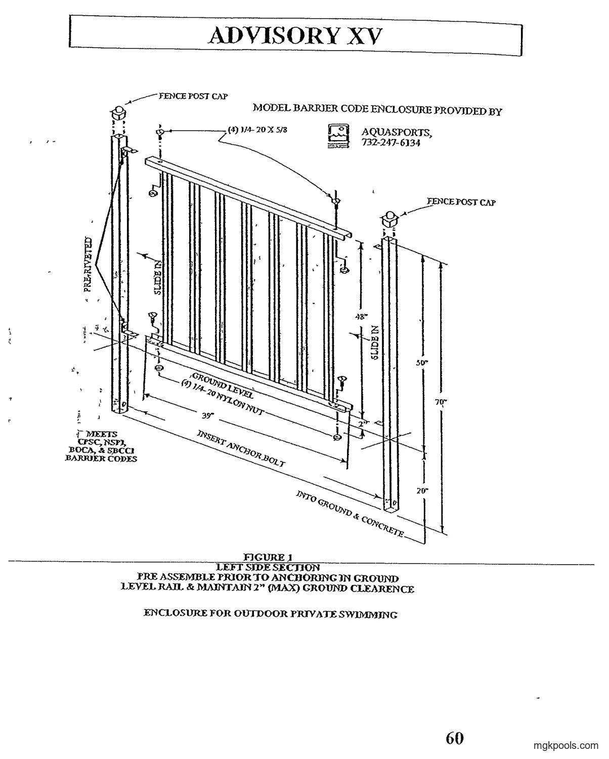
Labels printed in this drawing
- FENCE POST CAP (two posts, each labeled)
- (4) 1/4-20 X 5/8
- PRE-RIVETED
- SLIDE IN (two places)
- 48"
- 50"
- 70"
- 20"
- 2"
- 39"
- GROUND LEVEL
- (4) 1/4-20 NYLON NUT
- INSERT ANCHOR BOLT
- INTO GROUND & CONCRETE
- MEETS CPSC, NSPI, BOCA, & SBCCI BARRIER CODES
- FIGURE 1
- LEFT SIDE SECTION
- PRE ASSEMBLE PRIOR TO ANCHORING IN GROUND
- LEVEL RAIL & MAINTAIN 2" (MAX) GROUND CLEARANCE
ENCLOSURE FOR OUTDOOR PRIVATE SWIMMING
ADVISORY XV CONTINUED
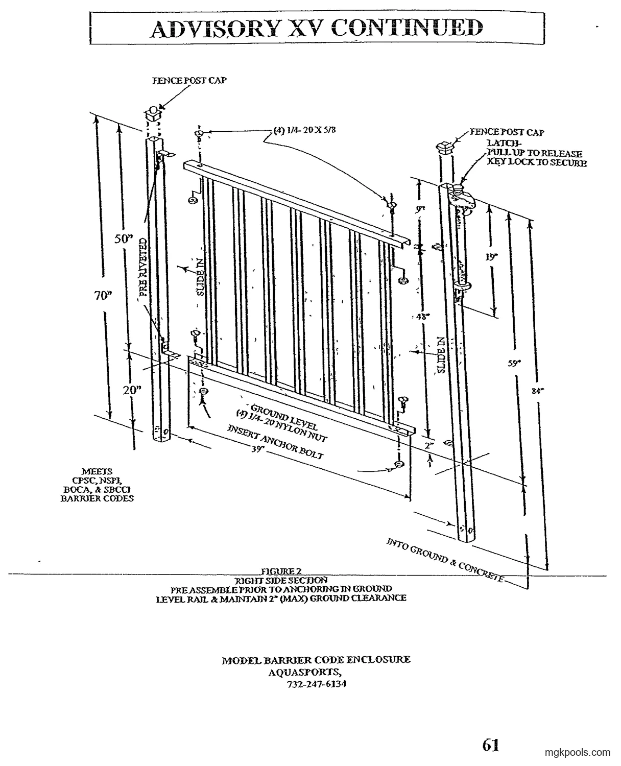
Labels printed in this drawing
- FENCE POST CAP (two posts, each labeled)
- (4) 1/4-20 X 5/8
- LATCH – PULL UP TO RELEASE, KEY LOCK TO SECURE
- PRE RIVETED
- SLIDE IN (two places)
- 50"
- 70"
- 20"
- 9"
- 19"
- 48"
- 59"
- 84"
- 2"
- 39"
- GROUND LEVEL
- (4) 1/4-20 NYLON NUT
- INSERT ANCHOR BOLT
- INTO GROUND & CONCRETE
- MEETS CPSC, NSPI, BOCA, & SBCCI BARRIER CODES
- FIGURE 2
- RIGHT SIDE SECTION
- PRE ASSEMBLE PRIOR TO ANCHORING IN GROUND
- LEVEL RAIL & MAINTAIN 2" (MAX) GROUND CLEARANCE
MODEL BARRIER CODE ENCLOSURE AQUASPORTS, 732-247-6134
ADVISORY XV CONTINUED
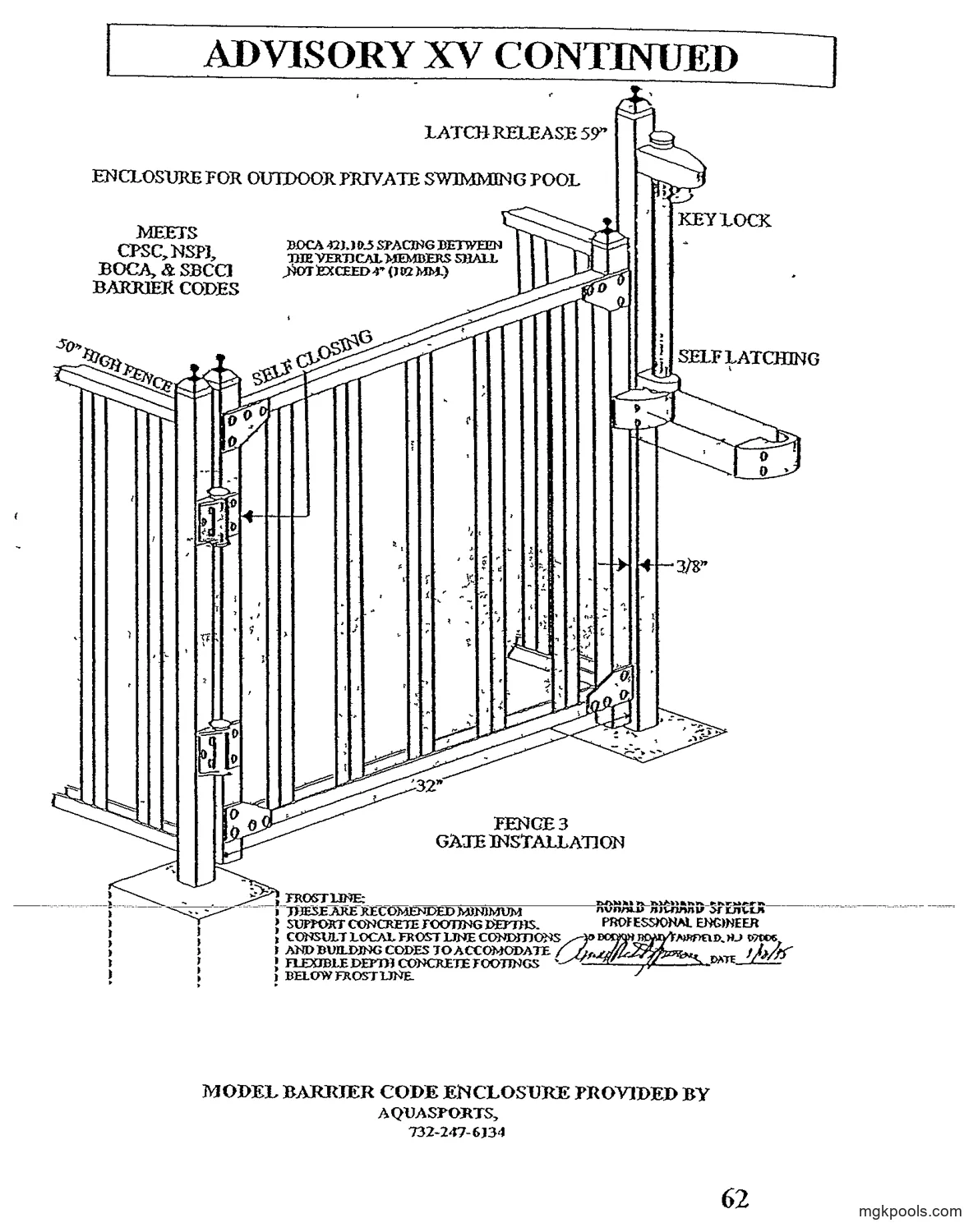
Labels printed in this drawing
- ENCLOSURE FOR OUTDOOR PRIVATE SWIMMING POOL
- LATCH RELEASE 59"
- KEY LOCK
- SELF LATCHING
- SELF CLOSING
- 50" HIGH FENCE
- MEETS CPSC, NSPI, BOCA, & SBCCI BARRIER CODES
- BOCA 421.10.5 SPACING BETWEEN THE VERTICAL MEMBERS SHALL NOT EXCEED 4" (102 MM.)
- 3/8"
- 32"
- FENCE 3
- GATE INSTALLATION
- FROST LINE: THESE ARE RECOMMENDED MINIMUM SUPPORT CONCRETE FOOTING DEPTHS. CONSULT LOCAL FROST LINE CONDITIONS AND BUILDING CODES TO ACCOMMODATE FLEXIBLE DEPTH CONCRETE FOOTINGS BELOW FROST LINE.
- RONALD RICHARD SPENCER
- PROFESSIONAL ENGINEER
- 10 [illegible] ROAD, FAIRFIELD, N.J. 07006
- (signature) DATE 1/[illegible]/95
MODEL BARRIER CODE ENCLOSURE PROVIDED BY AQUASPORTS, 732-247-6134
ADVISORY XV CONTINUED
REFER TO ISPSC-2021 (added on the 2026 stamped copy)
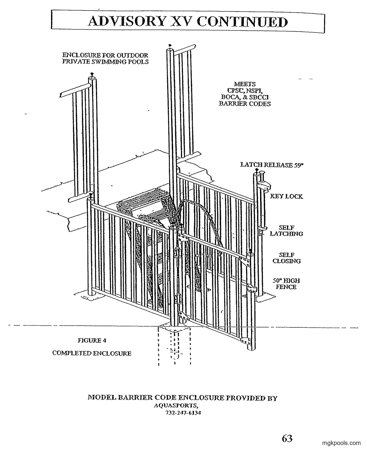
Labels printed in this drawing
- ENCLOSURE FOR OUTDOOR PRIVATE SWIMMING POOLS
- LATCH RELEASE 59"
- KEY LOCK
- SELF LATCHING
- SELF CLOSING
- 50" HIGH FENCE
- FIGURE 4
- COMPLETED ENCLOSURE
MODEL BARRIER CODE ENCLOSURE PROVIDED BY AQUASPORTS, 732-247-6134
ADVISORY XV CONTINUED
Aquasports, Enclosure for Above Ground, Outdoor, Private Swimming Pool * Requires Fourth Side Fence Enclosure Under The Deck To Secure Open Under Of Ladder * Not Illustrated
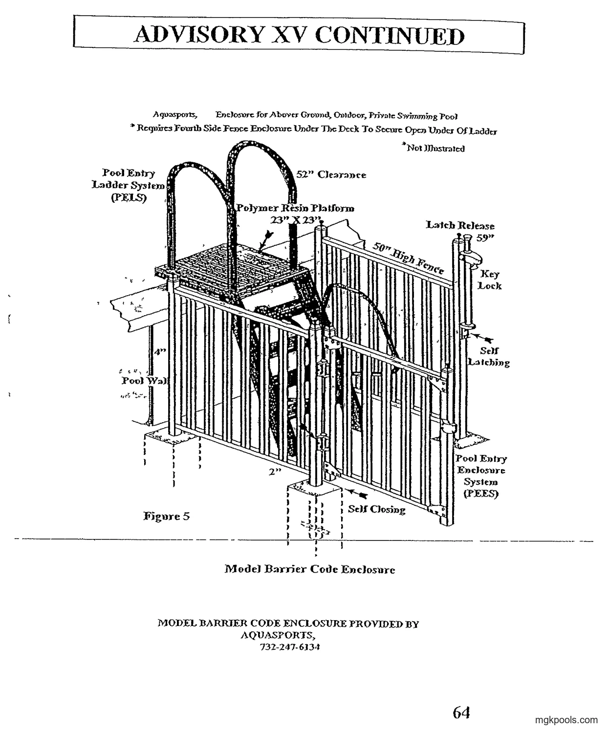
Labels printed in this drawing
- Pool Entry Ladder System (PELS)
- 52" Clearance
- Polymer Resin Platform 23" X 23"
- 50" High Fence
- Latch Release 59"
- Key Lock
- Self Latching
- Self Closing
- 4"
- Pool Wall
- 2"
- Pool Entry Enclosure System (PEES)
- Figure 5
- Model Barrier Code Enclosure
MODEL BARRIER CODE ENCLOSURE PROVIDED BY AQUASPORTS, 732-247-6134
ADVISORY XVI
BOCA EXCERPTS
REFER TO ISPSC-2021 (added on the 2026 stamped copy)
THE BOCA NATIONAL BUILDING CODE/1993 . . . OR LATEST REVISIONS, BOCA (PAGE 48-50) SPECIAL USE AND OCCUPANCY (continued):
THE BOCA (BUILDING OFFICIALS CODE OF AMERICA) CONSTRUCTION CODE HAS BEEN RELEASED. MANY JURISDICTIONS, LOCAL, MUNICIPAL, AND STATE HAVE ADOPTED THIS CODE. THE IMPLEMENTATION OF THIS CODE HAS CREATED A NUMBER OF MISUNDERSTANDINGS. WE WOULD LIKE TO HIGHLIGHT THE CODE FOR CLARITY. WE PRESENT FOR YOUR INFORMATION AND USE EXCERPTS TAKEN FROM THE BOCA CODE DATED 1993 AS FOLLOWS:
421.2 DEFINITIONS……….(SEE PAGE 48) PRIVATE SWIMMING POOL: ANY STRUCTURE THAT CONTAINS WATER OVER TWENTY-FOUR INCHES (610mm) IN DEPTH AND WHICH IS USED, OR INTENDED TO BE USED, FOR SWIMMING AND RECREATIONAL BATHING IN CONNECTION WITH AN OCCUPANCY IN USE GROUP R-3 AND WHICH IS ONLY AVAILABLE TO THE FAMILY AND GUESTS OF THE HOUSEHOLDER. THIS INCLUDES INGROUND, ABOVE GROUND, ON GROUND SWIMMING POOLS, HOT TUBS AND SPAS. PRIVATE SWIMMING POOL, INDOORS: ANY PRIVATE SWIMMING POOL THAT IS TOTALLY CONTAINED WITHIN A PRIVATE STRUCTURE AND SURROUNDED ON ALL FOUR SIDES BY WALLS OF SAID STRUCTURE. PRIVATE SWIMMING POOL, OUTDOORS: ANY PRIVATE SWIMMING POOL THAT IS NOT AN INDOOR POOL. PUBLIC SWIMMING POOL: ANY SWIMMING POOL OTHER THAN A PRIVATE SWIMMING POOL. SPA: SEE DEFINITION OF PRIVATE SWIMMING POOL.
421.10 ENCLOSURES FOR PRIVATE POOLS, SPAS, AND HOT TUBS: (PAGE 49): PRIVATE SWIMMING POOLS, SPAS, AND HOT TUBS SHALL BE ENCLOSED IN ACCORDANCE WITH SECTIONS 421.10.1 THROUGH 421.10.4 OR BY OTHER APPROVED BARRIERS.
421.10.1 OUTDOOR PRIVATE SWIMMING POOLS: AN OUTDOOR PRIVATE SWIMMING POOL, INCLUDING AN INGROUND, ABOVE GROUND OR ONGROUND POOL, HOT TUB OR SPA SHALL BE PROVIDED WITH A BARRIER WHICH SHALL COMPLY WITH THE FOLLOWING:
- THE TOP OF THE BARRIER SHALL BE AT LEAST 48 INCHES (1219mm) ABOVE FINISHED GROUND LEVEL MEASURED ON THE SIDE OF THE BARRIER WHICH FACES AWAY FROM THE SWIMMING POOL. THE MAXIMUM VERTICAL CLEARANCE BETWEEN FINISHED GROUND LEVEL AND THE BARRIER SHALL BE 2 INCHES (51mm) MEASURED ON THE SIDE OF THE BARRIER WHICH FACES AWAY FROM THE SWIMMING POOL. WHERE THE TOP OF THE POOL STRUCTURE IS ABOVE FINISHED GROUND LEVEL AS AN ABOVE GROUND POOL, THE POOL STRUCTURE, OR SHALL BE MOUNTED ON TOP OF THE POOL STRUCTURE. WHERE THE BARRIER IS MOUNTED ON TOP OF THE POOL, THE MAXIMUM VERTICAL CLEARANCE BETWEEN THE TOP OF THE POOL STRUCTURE AND THE BOTTOM OF THE BARRIER SHALL BE 4 INCHES (102mm).
ADVISORY XVI
BOCA EXCERPTS (CONT’D)
-
OPENINGS IN THE BARRIER SHALL NOT ALLOW PASSAGE OF A 4 INCH (102mm) DIAMETER SPHERE……….(PAGE 50)
-
SOLID BARRIERS SHALL NOT CONTAIN INDENTATIONS OR PROTRUSIONS EXCEPT FOR NORMAL CONSTRUCTION TOLERANCES AND TOOL MASONRY JOINTS.
-
WHERE THE BARRIER IS COMPOSED OF HORIZONTAL AND VERTICAL MEMBERS AND THIS IS BETWEEN THE TOPS OF THE HORIZONTAL MEMBERS IS LESS THAN 45 INCHES (1143mm), THE HORIZONTAL MEMBERS SHALL BE LOCATED ON THE SWIMMING POOL SIDE OF THE FENCE. SPACING BETWEEN THE VERTICAL MEMBERS SHALL NOT EXCEED 1-3/4 INCHES (44mm) IN WIDTH.
-
WHERE THE BARRIER IS COMPOSED OF HORIZONTAL AND VERTICAL MEMBERS AND THE DISTANCE BETWEEN THE TOPS OF THE HORIZONTAL MEMBERS IS 45 INCHES (1143mm) OR MORE, SPACING BETWEEN THE VERTICAL MEMBERS SHALL NOT EXCEED 4 INCHES (102mm). DECORATIVE CUT OUTS SHALL NOT EXCEED 1-3/4 INCHES (44mm) IN WIDTH.
-
MAXIMUM MESH SIZE FOR CHAIN LINK FENCE SHALL BE 1-3/4 INCHES (44mm) SQUARE UNLESS THE FENCE IS PROVIDED WITH SLATS FASTENED AT THE TOP OR BOTTOM WHICH REDUCE THE OPENINGS TO 1-3/4 INCHES (44mm).
-
WHERE THE BARRIER IS COMPOSED OF DIAGONAL MEMBERS SUCH AS A LATTICE FENCE, THE MAXIMUM OPENING FORMED BY THE DIAGONAL MEMBERS SHALL NOT BE MORE THAN 1-3/4 INCHES (44mm).
-
ACCESS GATES SHALL NOT COMPLY WITH THE REQUIREMENTS OF ITEMS 1 THROUGH 7 OF SECTION 421.10.1 AND SHALL BE EQUIPPED TO ACCOMMODATE A LOCKING DEVICE. PEDESTRIAN ACCESS GATES SHALL OPEN OUTWARDS AWAY FROM THE POOL AND SHALL BE SELF CLOSING AND HAVE A SELF LATCHING DEVICE. GATES OTHER THAN PEDESTRIAN ACCESS GATES SHALL HAVE A SELF LATCHING DEVICE. WHERE THE RELEASE MECHANISM OF THE LATCHING DEVICE IS LOCATED LESS THAN 54 INCHES (1372mm) FROM THE BOTTOM OF THE GATE: (a) THE RELEASE MECHANISM SHALL BE LOCATED ON THE POOL SIDE OF THE GATE AT LEAST 3 INCHES (76mm) BELOW THE TOP OF THE GATE; (b) THE GATE AND BARRIER SHALL NOT HAVE AN OPENING GREATER THAN 1/2 INCH (13mm) WITHIN 18 INCHES (457mm) OF THE RELEASE MECHANISM.
ADVISORY XVI
BOCA EXCERPTS (CONT’D)
-
WHERE THE WALL OF A DWELLING SERVES AS PART OF THE BARRIER ONE OF THE FOLLOWING SHALL APPLY 9.1 WALL DOORS WITH DIRECT ACCESS TO THE POOL THROUGH THAT WALL SHALL BE EQUIPPED WITH AN ALARM WHICH PRODUCES AN AUDIBLE WARNING WHEN THE DOOR AND ITS SCREEN, IF PRESENT ARE OPENED. THE ALARM SHALL SOUND FOR A MINIMUM OF 30 SECONDS IMMEDIATELY AFTER THE DOOR IS OPENED. THE ALARM SHALL HAVE A MINIMUM SOUND PRESSURE OF 85 dBA AT 10 FEET (3048mm) AND THE SOUND OF THE ALARM SHALL BE DISTINCTIVE OF OTHER HOUSEHOLD SOUNDS SUCH AS SMOKE ALARMS, TELEPHONES AND DOORBELLS. THE ALARM SHALL AUTOMATICALLY RESET UNDER ALL CONDITIONS. THE ALARM SHALL BE EQUIPPED WITH MANUAL MEANS, SUCH AS TOUCH PADS OR SWITCHES TO DEACTIVATE TEMPORARILY FOR A SINGLE OPENING FROM EITHER DIRECTION. SUCH DEACTIVATION SHALL LAST FOR NO MORE THAN 15 SECONDS. THE DEACTIVATION TOUCH PADS OR SWITCHES SHALL BE AT LEAST 54 INCHES (1372mm) ABOVE THE THRESHOLD OF THE DOOR. 9.2 THE POOL SHALL BE EQUIPPED WITH AN APPROVED POWER SAFETY COVER.
-
WHERE AN ABOVE GROUND POOL STRUCTURE IS USED AS A BARRIER OR WHERE THE BARRIER IS MOUNTED ON TOP OF THE BARRIER AND THE MEANS OF ACCESS IS A FIXED OR REMOVABLE LADDER OR STEPS, THE LADDER OR STEPS SHALL BE SURROUNDED BY A BARRIER WHICH MEETS THE REQUIREMENTS OF ITEMS ONE THROUGH NINE OF SECTION 421.10.1. A REMOVABLE LADDER SHALL NOT CONSTITUTE AN ACCEPTABLE ALTERNATIVE TO CLOSURE REQUIREMENTS.
421.10.2 INDOOR PRIVATE SWIMMING POOLS: ALL WALLS SURROUNDING AN INDOOR SWIMMING POOL SHALL COMPLY WITH 421.10.1, ITEM 9.
421.10.3 PROHIBITED LOCATIONS: BARRIERS SHALL BE LOCATED SO AS TO PROHIBIT PERMANENT STRUCTURES, EQUIPMENT OR SIMILAR OBJECTS FROM BEING USED TO CLIMB THE BARRIERS.
421.10.4 EXEMPTIONS: THE FOLLOWING SHALL BE EXEMPT FROM THE PROVISIONS OF THIS SECTION. 1. A SPA OR HOT TUB WITH AN APPROVED SAFETY COVER 2. FIXTURES WHICH ARE DRAINED AFTER EACH USE.
THE ABOVE INFORMATION HAS BEEN EXTRACTED FROM THE 1993 BOCA STANDARD. FOR COMPLETE SPECIFICATIONS PLEASE REFER TO CODE DOCUMENT. MOST JURISDICTIONS REQUIRE BARRIERS OR FENCING AROUND ALL POOLS. CONSULT YOUR LOCAL BUILDING OFFICIALS TO DETERMINE THE APPLICABLE REQUIREMENTS.
ADVISORY XVII
The following is reprinted with permission from the Consumer Product Safety Commission.
Consumer Product SAFETY ALERT
FROM THE U.S. CONSUMER PRODUCT SAFETY COMMISSION, WASHINGTON, D.C. 20207
July 1991
Prevent Electrocutions:
Install Ground-Fault Circuit-Interrupter Protection for Pools, Spas, and Hot Tubs
The U.S. Consumer Product Safety Commission (CPSC) recommends the installation of ground-fault circuit-interrupter (GFCI) protection for consumers against electrical shock hazards in pool underwater lighting circuits and in electric circuits of spas and hot tubs.
CPSC is aware of three recent electrical shock incidents involving the electric heater circuits of spas or hot tubs. Recently, a maintenance worker was electrocuted while repairing a pool light fixture.
A GFCI constantly monitors current flowing in a circuit to sense any loss of current. If the current flowing through two circuit conductors differs by a very small amount, the GFCI instantly interrupts the current flow to prevent a lethal amount of electricity from reaching the consumer. The consumer may feel a painful shock but will not be electrocuted.
The National Electrical Code provides for GFCI protection for cord-and-plug connected spas and hot tubs, and for lighting fixtures and receptacle outlets in the vicinity of pools, spas and hot tubs. However, the code does not require GFCI protection for all electrical equipment, particularly 240 volt equipment. Older pools, spas and hot tubs may not have adequate GFCI protection. In particular, pools older than 10-15 years may not have GFCI protection on underwater lighting circuits. Underwater swimming pool lighting fixtures and spa/hot tub heaters are a potential source of electrocution. Both 120 volt and 240 volt circuits should be protected by GFCIs.
Although grounding may provide some protection for pool, spa, and hot tub equipment, GFCIs are the most effective means for protecting consumers against electric shock hazards.
CPSC urges consumers to have an electrician install adequate GFCI protection for all spa and hot tub electrical equipment and for underwater swimming pool lighting fixtures.
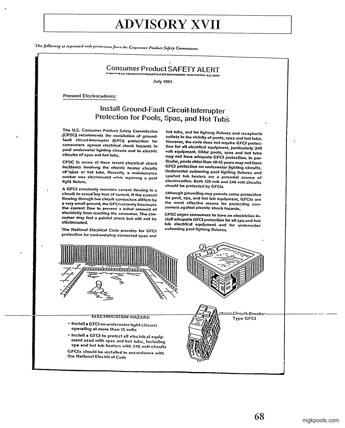
Labels printed in this drawing
- (no text inside the drawing)
Labels printed in this drawing
- (no text inside the drawing)
Labels printed in this drawing
- Circuit Breaker Type GFCI
ELECTROCUTION HAZARD
- Install a GFCI on underwater light circuits operating at more than 15 volts.
- Install a GFCI to protect all electrical equipment used with spas and hot tubs, including spa and hot tub heaters with 240 volt circuits.
GFCIs should be installed in accordance with the National Electrical Code.
ADVISORY XVIII
Labels printed in this drawing
- (no text inside the photograph)
When your car breaks down you bring it to a certified mechanic. When your plumbing backs up, you call in a licensed plumber. Why trust your pool to anyone less than a proven professional?
IF YOU’VE GOT A POOL – GET A PROFESSIONAL
Labels printed in this drawing
- (no text inside the photograph)
A clean, safe, enjoyable pool and spa can best be maintained by a qualified professional. We employ NSPI CERTIFIED pool technicians with proven excellence in pool and spa maintenance. The NSPI CERTIFIED pool technician has passed comprehensive standard examinations and training. Don’t trust your pool to anyone less than the best.
We are a proud member of NSPI, the National Spa and Pool Institute, a trade association for professionals in the pool and spa industry. We offer NSPI CERTIFIED technicians on staff.
Labels printed in this drawing
- NATIONAL SPA & POOL INSTITUTE
- CERTIFIED
Parts, liners and help
- Aquasport 52 pools for sale
- Aquasport 52, the brochure page with specs and reviews
- Aquasport Pools, the manufacturer
- semi inground pool kits
- semi inground pool buyer’s guide
- semi inground pool cost
- replacement above ground pool liners
- pool bonding kit
- Pool light kit
- semi-inground pool installation in Massachusetts
- contact Mike